How To - Motor Balancing
|
Introduction
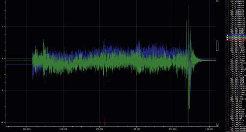
Getting into the crazy quad world has been great fun and a great learning adventure. When I started taking video I found pretty quickly that the cameras I have, all with "rolling shutter" CMOS sensors, are extremely sensitive to vibration. I first tried isolating the camera with foam, moon gel, rubber, etc. as well as prop balancing. These methods went a long way to elliminating the "jello" effect I was seeing in my videos but sometimes there was still some jello. With that, I started looking for a way to dynamically check and balance the motors too. I do this now on all my planes as well.
First - A checklist for vibration elimination
Here are a few things to check or change in your hunt for a smoother running airframe:
- 1. If you have a gimbal, especially a brushless gimbal, make sure the vibration is not coming from the gimbal motors. Re-tune the gimbal controller if this is the case.
- a. Move the gimbal mount to be as close to the CG as possible. The CG is where the magnitude of vibration is lowest.
- b. Try hard mounting or more firmly mounting the gimbal, sometimes the damping is the cause (too soft).
- 2. Do not use cheap plastic props like GemFan. They track poorly and do not hold their shape under load (and they are noisy).
- 3. Do not use cheap Carbon Fiber propeller clones like RCTimer and Foxtech. They track poorly and are generally too stiff to work efficiently.
- 4. Make sure all motor mount, prop adapter and gimbal frame screws are tight.
- 5. Check that all motor shafts and prop adapters are perfectly straight. No amount of balancing or damping will cure a bent shaft.
- 6. Check that every prop tracks, tip to tip, at least within .4mm (.015"). No amount of balancing or damping can cure a poorly tracking prop.
- 7. Balance all props on a mag balancer (see Propeller Balancing)
- 8. Balance the motors. Even expensive ones need this sometimes, inexpensive ones (like NTM) always need balancing.
- 9. If you still have unacceptable jello, consider changing propeller size and motor Kv to change the vibration frequency.
In my search for ways to do the motor balancing part I happened on this excellent video from one of the posters, "pajonate", on RCGroups.com. He does a great job of outlining the process of dynamically balancing outrunner motors and this is the basis for this How-To.
|
pajonates original motor balance video |
Tools, Bits and Pieces You Will Need
The following list is everything you will need to set up for balancing your motors:
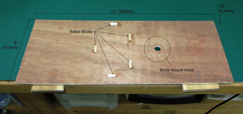
What you need What I used A smart phone with a vibration APP iPhone 4 Small board drilled for your motor 1/4" (6mm) plywood, 6" x 15" Tachometer (optional) HK Kv/RPM Meter An ESC 25 AMP Dynam ESC Servo Tester HK Servo Tester Clamps 2" Squeeze clamps Tape for counter weight Blenderm Tape
First - The Motor
Before spending the time to do this, make sure the motors are up to the task and in good working order.
- Check that all shaft clips or screw collars are securely seated or fastened
- Check all propeller adapter screws for tightness
- Spin the motor by hand and make certain there is no resistance or any contact between magnets and stator
- Prior to mounting, lubricate the bearings with a high quality synthetic motor oil or Scorpion motor lube

|
| Scorpion Oil kit |
- This is a good time to check that the bullet connectors are securely soldered and tight
- Power the motor up without a prop and make certain the propeller adapter spins without any wobble (very important!)
- Clean the motor bell with denatured alcohol for better tape adhesion
iPhone APP
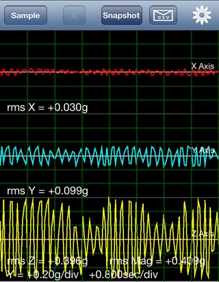
I found another APP, "Vibration" ($4.99) for the iPhone which like the one shown in the pajonate video, gives three axis of data and is adjustable for scale and length of time for the test. I like this one a little better because when you start a new test it clears all the previous test data. It also has a nice feature for capturing the data to view and analyze later.
|
| APP - "Vibration" |
Note:
Both APPs give results in "g's". If you are not familiar with this term, a "g" is a unit of force equal to the force exerted by gravity. In any case, a smaller number is always better as you will see. You will also see a number for "rms MAG" and this is an indication of the combined magnitude of all three measures. Again, a smaller number here is better.
Test Board
The test board is simple with drilled holes for the motor mount and 5 small blocks of balsa to keep the iPhone from moving around. You will also need to secure the board on some scrap pieces with clamps to a bench or table. The scrap gives clearance for the motor mount screws and/or shaft and allows the board to vibrate freely.
|
| Test board |
Tachometer
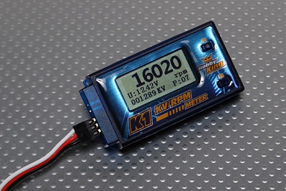
The tachometer, which is optional, can be any style that you can read hands free. That is, a digital display so you can easily adjust the RPM.
|
| Tachometer used |
ESC
Any standard ESC should work well. I used a Dynam unit from DW Foamies and it worked well with the servo tester I have.
Servo Tester
The servo tester is used to activate the ESC and adjust the RPM. Any servo tester should work or you could use a receiver and your transmitter but this may be harder to get fine RPM adjustments.
Clamps
The clamps are to secure the board to a bench or table.
The Test Set-Up
To get started follow these instruction for the test board set-up:
- 1. Attach the motor to its mount and the test board. Make sure all fasteners are tight.
- 2. Place the board on pieces of scrap wood and secure it to a bench or table. Only clamp scrap under the ends so the middle of the board can freely vibrate.
- 3. Connect the ESC, the tachometer (if used) and the servo tester or TX/RX. Support all wires so that nothing touches or lays on the test board.
- 4. Mark the motor bell with four test points.
- 5. Set the smart phone onto the board in its position blocks, turn it on and select the vibration app.
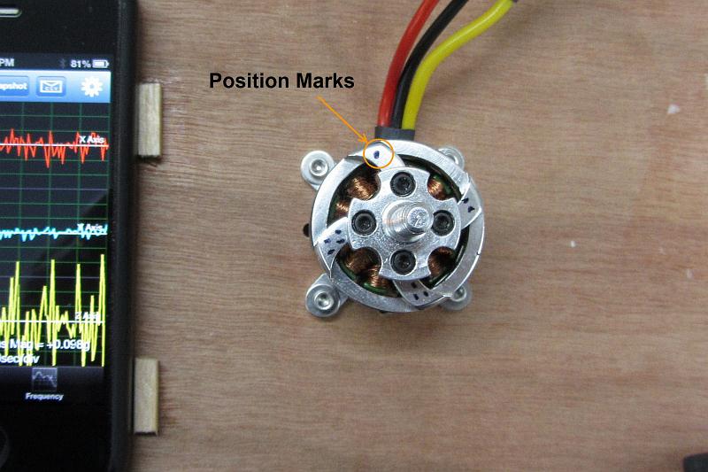
|
| Motor Marking |
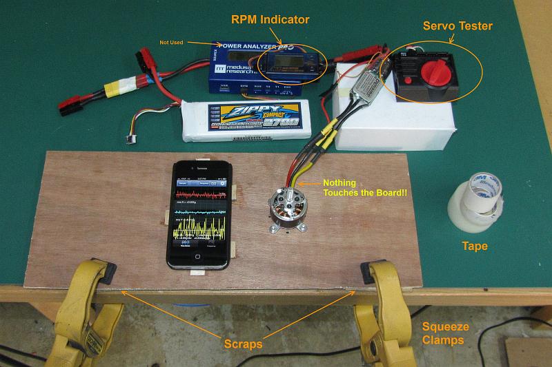
|
| Ready to Test |
Another Test Set-Up
If you don't want to go to the trouble of making a test board, you can do the balancing directly on your multi-rotor. You simply need to have a way to firmly hold the phone against the frame as shown below on my HT-FPV frame. One thing to note here, you likely won't see nearly the vibration magnitudes doing it this way as the board method (above) tends to amplify the vibration making it easier to see and eliminate vibration.
- 1. Attach the phone to the frame. Make sure all fasteners are tight.
- 2. Place the frame such that it is not sitting on the frame legs (important!).
- 3. Connect one ESC signal, the tachometer (if used) and the servo tester or TX/RX.
- 4. Mark the motor bell with four test points.
- 5. Turn on the phone and select the vibration app.
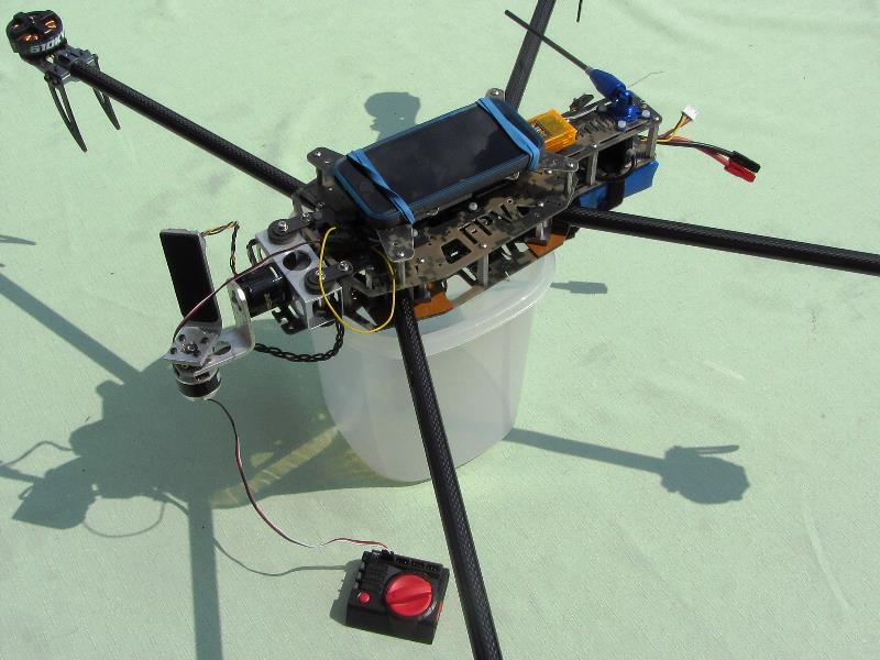
|
| Direct mounting method |
Test Procedure
The following illustrates correct tape placement:
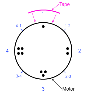
|
Test Sequence
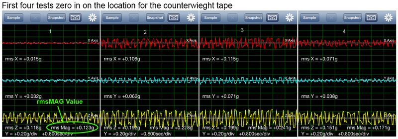
The first set of tests will run the set-up nine times. This will give you the spot where the imbalance is on the motor bell. For this example I started with a 1/2" x 3/4" piece of tape. When you run the motor, select "Sample" on the iPhone APP and let it complete to see the results. In some cases your motor will be out of the box balanced so the first run is to set a reference value. If all subsequent test have higher results, the motor is already balanced.
- 1. If you are using a tach, run the motor to find where it is noisiest and write down the RPM and the value on the phone App for rmsMAG. Run every subsequent test for that motor at the same RPM.
- If you are not using a tach run the motor full speed and write down the rmsMAG value (faster but not as accurate).
- 2. Now, run the first four tests:
- a. Starting with the #1 spot, place a 3/4" (19mm) piece of 1/2" tape on the outside of the bell so that the spot is centered on the tape, run the motor and write down the rmsMAG value.
- b. Remove the tape from spot #1 and place it centered at spot #2, run the motor and write down the rmsMAG value.
- c. Remove the tape from spot #2 and place it centered at spot #3, run the motor and write down the rmsMAG value.
- d. Remove the tape from spot #3 and place it centered at spot #4, run the motor and write down the rmsMAG value.
- You now have 5 values to consider, remember; a lower number is better. For this example, you see following values:
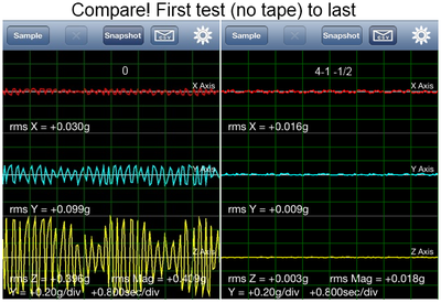
- Spot 0 (no tape) +0.409
- Spot 1 0.123g
- Spot 2 0.228g
- Spot 3 0.241g
- Spot 4 0.171g
- You now have 5 values to consider, remember; a lower number is better. For this example, you see following values:
|
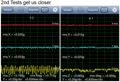
- 3. Now you know that the point at which you need to add weight is near #1, so two more runs:
- a. Remove the tape from spot #4 and place it centered between spot #4 and spot #1, run the motor and write down the rmsMAG value.
- b. Remove the tape from between #4 and #1 and place it centered between #1 and #2, run the motor and write down the rmsMAG value.
- Now you have two additional values to consider:
- Spot 4-1 0.066g (WINNER!)
- Spot 1-2 0.175g
- Now you have two additional values to consider:
|
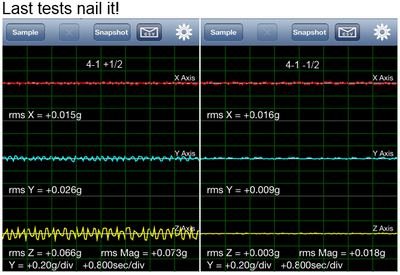
- 4. Last tests! The last tests determine how mach tape to add so the tape is placed at the #4-1 (between 4&1). Add 1/2 the amount more & less for the last two runs.
- a. Add a piece 1/2 as big as the original over and centered on the piece at #4-1, run the motor and write down the rmsMAG value.
- b. Remove the 1/2 piece and cut the original in half and re-center it on the motor at #4-1, run the motor and write down the rmsMAG value.
- Results!
- Spot 4-1 +1/2 0.073g
- Spot 4-1 -1/2 0.018g
- Results!
|
|
- 5. Replace the tape with new, fresh piece(s) and don't forget to clean the motor bell.
Critical for Good Results
- 1. Once set-up and everything is working properly, do not change any part of your set-up until you are completely finished with all tests. If you disconnect, loosen, tighten or move anything on the board, you will get different results that may not look the same and you may have to start over.
- 2. Do not let anything touch (especially fingers!) or lay across the board while the test sample is running as this could dramatically affect the results.
- 3. Make sure you know how to use the phone APP and don't change APP settings once you start the test.
First things last - Don't forget your Props!
Even though many of our props are very light, they must be balanced! In my shop I use a magnetic balancer by Top Flight which can be picked up for around $20 at Tower or most local hobby stores. I have also modified my balancer to use a short, threaded "Finger Tip Balancer" which helps with sensitivity and accuracy. It is an easy modification that simply involves shortening the two spreader bars so that the shorter finger balance shaft fits between the magnets with a small (~.008"/0.2mm) gap on one end.
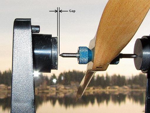
|
| Shorter finger balance shaft with gap on one end |
The process is simple, thread the balance shaft through the prop with all bushings installed, set it in the balancer and add tape to the light end till the prop stays level. Make sure there are no plastics or your hands nearby while balancing as plastic props can be very sensitive to static charge. I actually step away from the balancer a bit to insure this. For plastic props I use scissor cut Scotch tape wrapped tightly around the leading edge near the tip so no edges are subject to peeling back under power. For wood props I use either tape or paint the light end with a very thin coat of lacquer. Note: Also make sure there is no air movement while balancing.
Once level you may notice that the prop will only stay level in one orientation. That is, the hub is slightly heavy on one side so if you turn the prop 180 degrees to level and let it go, it will rotate back around 180 degrees to the 1st side. This is normal, especially with a balancer this sensitive and in this case mark the hub on the side that is still heavy with a sharpie. Align this heavy-side mark with the center of the balance tape you put on the motor to keep the components aligned. It is unlikely the hub is so heavy on one side it will throw the motor balance off. If you think it has, you can try removing a very small piece of motor balance tape (be careful here).
Balancing a Folder - Tips to make it easy
Balancing a folder can be challenging so here are a few tips I use to make it easier and get good results.
Make it Flat and Long
- This means, make it like an ordinary fixed prop. To do this, tighten the blade screws enough to hold the blades flat and straight (not "floppy").
- Next lay it flat on a table or bench so the hub (with stop plates if used) is flat on the surface and the blade tips are just touching the table top.
- With the prop in this position, use a plastic or wooden dowel and gently pry each blade out so it is firmly against the pivot screw in the outward direction. This removes the slack and very closely emulates where the blade will sit while spinning.
- Check that the hub is still flat with the blade tips touching then move the prop to the mag balancer and follow the process outlined above.
That's it, now go make em smooth!
Video Sample
The following video was shot from my TBS Disco quad running HK NTM2826-1000 motors which are never well balanced out of the box. The gimbal used is my own brushless set-up and had very little vibration damping between the gimbal and the quad frame. The camera is hard mounted in the gimbal frame.
|
Our home in the Northwest |
See Also
Vendors used for this project
Comments? Questions?