Laser GCODE Conversion Method
| |
Introduction
Creating Laser GCODE
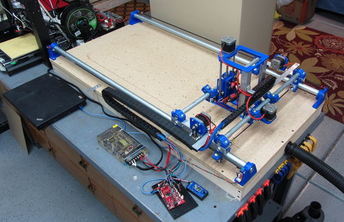
The following is my method for creating gcode files to be cut on my Bench-top CNC Laser
CAD Work to get a DXF
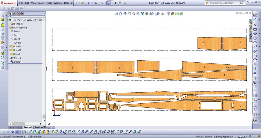
In my design software (SolidWorks in my case) after completing all part design I layout all similar thickness parts in an assembly, fitting them to virtual 4" x 36" balsa sheets.
|
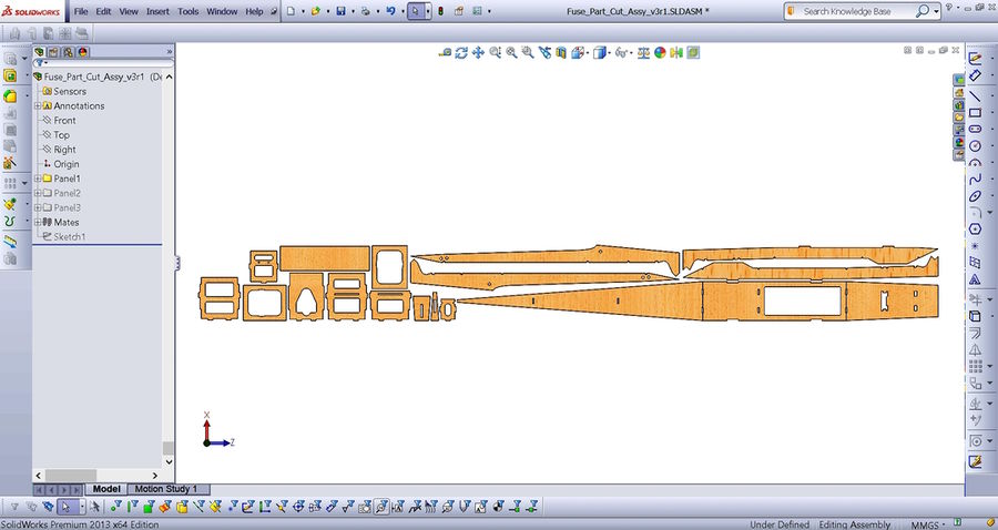
In the above example I have laid out all the parts of a fuselage build within three 4" x 36" panels represented by the dashed boxes. Once the layout is done I group each panel into three folders to represent the three panels. This gives me the ability to suppress each panel so I can send just one to a DXP drawing.
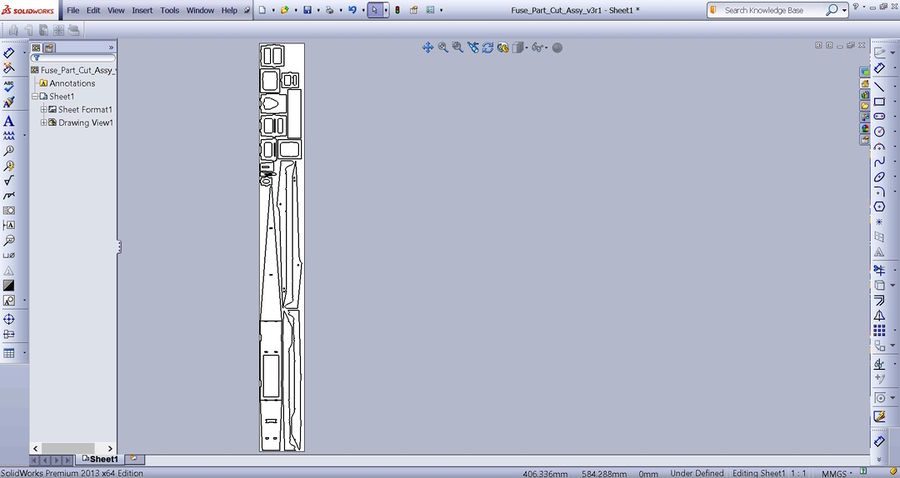
I then (in SolidWorks) create a drawing from this assembly making the drawing size 4" x 36" and set the X and Y axis to the part edges.
|
|
Once this is done I save the drawing as a DXF. I then go back and suppress this first panel and un-suppress the next panel, saving it as the next DXF. Note: I also suppress the dashed box as it is not needed in the DXF file.
I am now ready to convert these three DXF files to a workable gcode file.
DXF to GCODE
In my method there are three steps to this conversion.
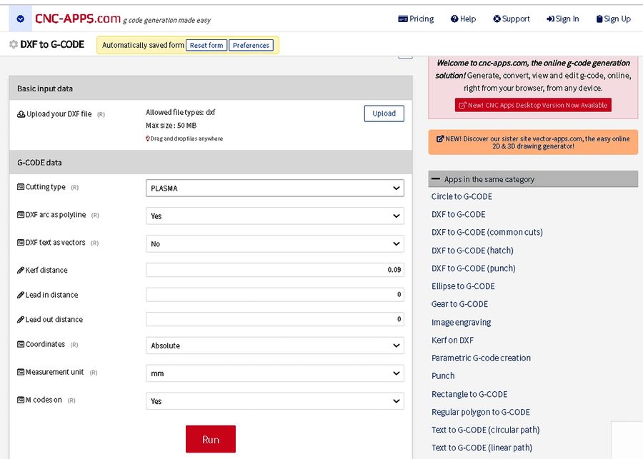
Step one is to upload each DXF to an online conversion tool and get a generic gcode file. I use the free converter found at "CNCAPPS.com". It is very easy to use and in my experience, has never written a bad or missed instruction.
Link: DXF to GCODE Converter
|
The parameters I set to run the converter are:
Cut type - Plasma (This allows a kerf adjustment and cuts all inside holes first)
DXF arc as polyline - Yes
DXF text as vectors - No
Kerf Distance - 0.09mm
Lead in distance - 0.0
Lead out distance - 0.0
Coordinates - Absolute
Measure unit - mm
M codes on - Yes
Now you hit the "RUN" button and in a few seconds (up to a minute) three file types are offered for download. I use the "GCODE" file type.
Step two is all about editing/check/clean-up. You can edit the file in any text editor. I use "Notepad++". This is a really nice code editing tool that I have written macros in to do all the file edits.
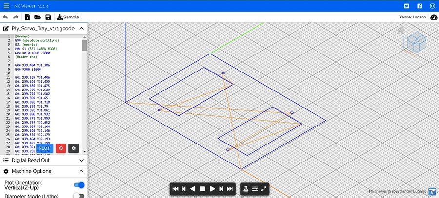
For the check part of this step, I use the free web based simulator "NC Viewer" at NCVIEWER.com
|
Upload your edited gcode file and hit the play button. You can watch the cut sequence while it draws through your shapes. The different colored lines represent paths for laser-off transit (Red) and laser-on cut (Blue). This is the clean-up part of this step and is a great way to check the quality of your gcode and isolate areas where you may want to make other changes.
RunIt!
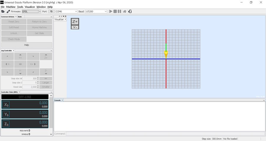
File should be ready to send to the laser. In my case I use UGS Platform which is another awesome freebie...
|
Referenced Links