DIY - RPM and Temperature Data Logger
© Mark Qvale - July, 2019
| |
| DIY Test Tool |
Introduction
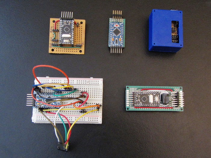
Folks on RCGroups and FB have asked about some of the test tools I use to get the recommendations, charts and numbers I use in my posts. This article then describes one of those tools which has been in continuous development for some time.
This DIY tool came from a need to be able to test components at steady state power, current and RPM levels to fully understand the loads being placed on the components. The first version of this served to regulate the RPM at a steady state regardless of voltage supply to test battery packs and ESC's. I then re-created the tool to regulate the current pulled from the ESC to further test battery packs in a controlled environment without the need for an expensive lab quality power supply.
The latest effort was to work out what the best props are to use for an FPV fixed wing project. To do this I needed to be able to put the tool in a plane and capture the RPM and motor temp. The first way to do this is to program the flight controller and micro controller to display (OSD) and log these values. Another way, and the one described here, was to make the tool stand-alone with its own data logging capability so I could move it from plane to plane regardless of flight controller set-up.
Tool Description
The tool captures RPM and two temperature values and logs them to a Micro SD card as a CSV file type which can be read and analyzed in MS Excel.
- RPM is captured using a Hobbywing RPM sensor which is the same as the Eagle Tree and Spektrum RPM sensors.
- RPM can be set using the TX while flying as either direct pass-through or regulated rpm.
- Temperature is captured using two glass bead NTC3950 thermistors commonly found on 3D printer set-ups.
- One temp sensor is epoxied onto the motor cross mount and the other is slipped under the ESC shrink cover on the heat-sink side.
- One extra radio channel is needed to activate the pass-through/regulated functions.
Parts
The following are the parts used in the latest version of this tool-
- 1. Arduino 5v/16mhz Pro Mini Board
- 2. Omron 5v SPDT Signal Relay
- 3. Hobbywing RPM Sensor
- 4. NTC3950 Thermistors
- 5. Pin headers
- 6. Double Sided Prototyping PCB
- 7. 2x 100k Ohm, 1/4 watt resistors
- 8. 2x 10nF (103) capacitors
Part descriptions
Arduino Pro Mini - I wanted a small board with enough IO to handle all the tasks. The Pro Mini or the Arduino Nano both easily fit the bill as does the Teensy LC board. The Pro Mini was finally selected because it works and I can find them for around $5 each.
Omron Relay - After trying many different software attempts to create a smooth pass-through mode for the signal from the flight controller directly to the ESC, I finally decided to use the normally closed side of a relay to accomplish this task. There are two reasons for this-
- 1. If the board fails for some reason the relay will close to direct pass-through making it possible to continue flying the plane.
- 2. Having a direct, hard wired pass-through makes it completely smooth which is important in how the regulated section of the software works.
- 3. Inexpensive ($1.79)
HobbyWing RPM Sensor - I actually started with an early Eagle Tree unit that had an issue with how the power wires were from the factor - Black = Positive, Red = Negative. While looking for a replacement I found the HobbyWing version which according to my O-scope produces the same output. Bonus is they are less than a quarter of the price of the Eagle Tree units ($4.49)
NTC3950 Thermistors - I selected this type of temp sensor because I had them already and they are really inexpensive ($1.40 ea). Also they are very easy to attach to the motor and ESC because of their size.
All together then, the parts for a single build cost me ~$18 plus any shipping.
Schematic
The schematic for this build can be seen here-
| 900px |
Board Build
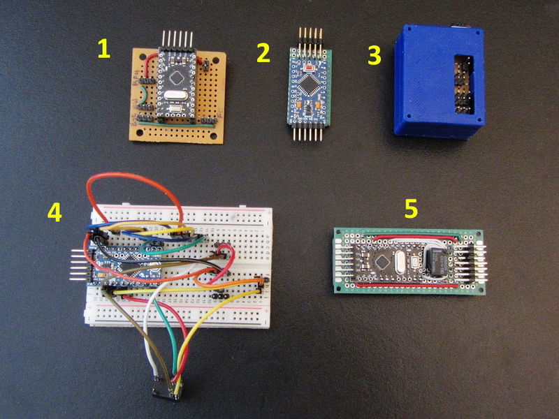
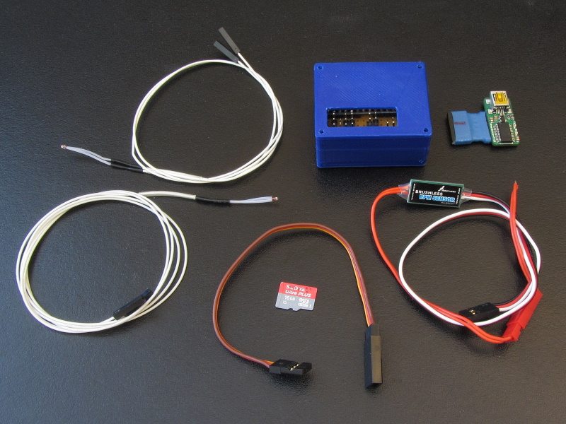
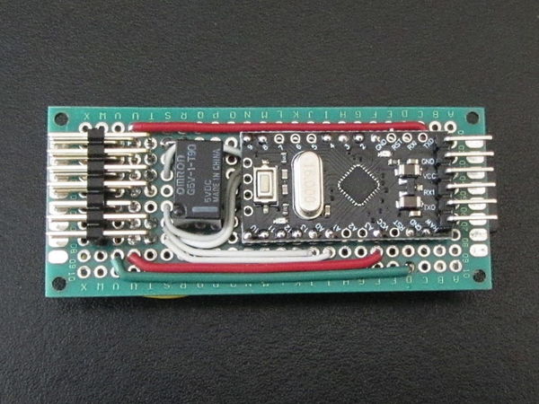
Here are some images of the first few versions and close-ups of the latest build-
|
Some of the proto set-ups
|
|
| First flight set-up |
|
| Current board (top) |
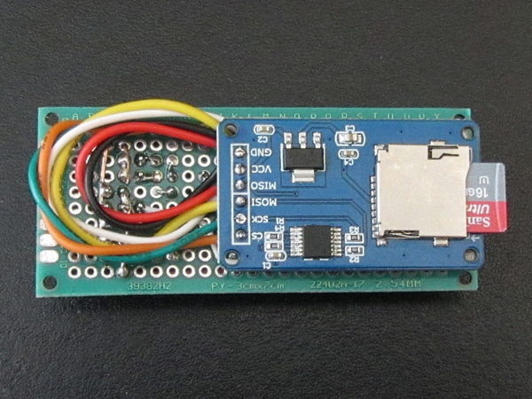
|
| Current board (bottom) |
Code
Copy the following into a new Arduino sketch and load to the board-
 /*
v15r1 - Added SPDT signal relay (mechanical) to get hard wired
pass-through and normally closed safety if there is a board fail.
*/
/*Project Details
  Brushless motor ESC, adjustable (in flight) RPM regulator with
  two temperature probes and data capture.
  ©Mark Qvale, 2019
  Creative Commons Attribution-ShareAlike 3.0 License

  Arduino Board and Pins used-
  Board - Arduino Pro Mini, Atmega 328P, 5v, 16mHz
  Pin 2 - RPM rpm sensor pin
  Pin 8 - Passthrough/Regulated switch channel
  Pin 9 - ESC out
  Pin 3 - RX/FC throttle in
  Pin 4 - Relay trigger out

  Arduino bord to Micro SD Card Shield Pins-
  Pin 10 - CS
  pin 11 - MOSI
  pin 12 - MISO
  pin 13 - SCK(CLK)

  Items needed for this build-
 1x Hobbywing RPM sensor for brushless motors
 2x 100k or 10k thermistors
 1x Nano or Pro-Mini board
 1x Micro SD card shield
 1x SPDT Signal relay, 5v
 2x R1 resistors (see below)
 2x 10nF (103) capacitors (to stabilize temp readings)

 Temp sensor & resistors-
 Glass bead thermistor 100k NTC3950
   R1 = 100K ohms
 10k thermistor
   R1 = 10K ohms
 Pin A0 is Temp 1 input
 Pin A1 is Temp 2 input

 Acknowledgements-
 Tom Igoe for his data log example code
 Adrian Li for the RPM counter section found at https://www.locarbftw.com/using-an-arduino-to-read-rpm-from-the-hobbywing-rpm-sensor/
*/

#include <Servo.h>                                        // Servo control library - Servo (built-in) by Michael Margolis
#include <Filter.h>                                       // Filter library - MegunoLink by Number Eight Innovation
#include <PID_v1.h>                                       // Control Loop library - PID by Brett Beauregard
#include <PWM.hpp>                                        // PWM reader library by Kamran Ahmad
#include <SPI.h>                                          // Serial Peripheral Interface library by Arduino
#include <SD.h>                                           // SD Card library by Arduino/Sparkfun
#define INTERRUPT_PIN 0                                   // defines pin 2 (0) as RPM interrupt

Servo escout;                                             // create servo/esc object

/* adjustable variables for signal smoothing  and PID parameters */
int rpmRND = 25;                                          // rounding value for rpm signal (default 25)
int EFW = 10;                                             // exponential filter weight (default 10)
int EFWB = 20;                                            // exponential filter weight (default 20)
int PST = 50;                                             // PID sample time (default 50)
float kP = 0.07;                                          // PID proportional factor
float kI = 0.03;                                          // PID integral factor
float kD = 0;                                             // PID derivative factor
int avgN = 20;                                            // temperature average number (default 20)
int period = 200;                                         // data print period in ms (default 200)
float numpoles = 14;                                      // number of motors magnet poles

/* global variables */
const int chipSelect = 10;                                // data write pin number
unsigned long time_now = 0;                               // print timer variable
volatile int interruptCount;                              // RPM count variable
unsigned long time = 0;                                   // initialize time variable
int csw = 0;                                              // switch state key 0
int nsw = 1;                                              // switch state key 1
int switchState;
int relay = 4;                                            // relay pin
int sig;                                                  // lower limit PWM signal variable
int thout;                                                // regulated ESC throttle output variable
float thpwm;                                              // RX/FC throttle input variable
float thrP = 0;                                           // throttle percent variable
int tempPin0 = A0;                                        // temperature read/compute variables
int tempPin1 = A1;                                        //
int Vo0;                                                  //
int Vo1;                                                  //
float avgT1;                                              //
float avgT2;                                              //
float R1 = 10000;                                         //
float logR2, R2, logR3, R3, T1, T2;                       //
float c1 = 1.009249522e-03;                               //
float c2 = 2.378405444e-04;                               //
float c3 = 2.019202697e-07;                               //

PWM thrIn(3);                                             // setup pin 3 for throttle input using the PWM ibrary

/* Exponential filter setup */
ExponentialFilter<long> ADCFilter(EFW, 0);                // rpm smoothing filter
ExponentialFilter<long> ADCFilterB(EFWB, 0);              // throttle signal smoothing filter

/* PID controller setup */
double rpmset, rpm, pwmsignal;                            // define variables connected to the PID controller
PID myPID(&rpm, &pwmsignal, &rpmset, kP, kI, kD, DIRECT); // PID tune set-up (original PID tune values - 2,5,1)

void setup()
{
  Serial.begin(115200);                                   // start the serial monitor
  rpm = 0;                                                // initialize rpm variable
  rpmset = 0;                                             // initialize PID variable, rpmset
  thrIn.begin(true);                                      // begin reading throttle input (3)
  escout.attach(9);                                       // attach ESC object (9)
  pinMode(relay, OUTPUT);                                 // relay on/off switch pin (4)
  pinMode(8, INPUT);                                      // set pinmode on RX switch pin (8)
  pinMode(INTERRUPT_PIN, INPUT);                          // set pinmode on RPM pin (2)
  attachInterrupt(INTERRUPT_PIN,interruptFired, CHANGE);  // set-up interrupt count on RPM pin (2)
  myPID.SetSampleTime(PST);                               // PID sampling rate in milliseconds (default = 50)
  myPID.SetMode(AUTOMATIC);                               // set PID mode, AUTOMATIC or MANUAL
  myPID.SetOutputLimits(900, 2000);                       // set low and high pwmsignal limits
  Serial.print("Initializing SD card...");                // see if the card is present and can be initialized
  if (!SD.begin(chipSelect)) {                            //
    Serial.println("Card fail, or not present");          //
    while(1);                                             //
  }
  Serial.println("card initialized.");                    //
  File dataFile = SD.open("Data_Log.csv", FILE_WRITE);    // name and open the CSV file
  if (dataFile) {
    dataFile.println("Time(s),Temp 1(F),Temp 2(F),RPM,Thr %,Switch");     // write the column headings to the csv file
    dataFile.close();                                     // close file
  }
}

void loop(){
  time = millis();                                        // time in ms
  thpwm = thrIn.getValue();                               // capture throttle signal
  ADCFilterB.Filter(thpwm);                               // throttle signal filter
  thpwm = ADCFilterB.Current();                           //

// +++++++++++++++++++++++++++++++++++++++++++ Throttle Percent ++++++++++++++++++++++++++
  thrP = thpwm;                                           // copy throttle signal value
  thrP = constrain(thrP, 990, 2010);                      // constrain values for mapping
  thrP = map(thrP, 990, 2010, 0, 100);                    // map throttle values to percent throttle

// +++++++++++++++++++++++++++++++++++++++++++ Temp 1 & 2 ++++++++++++++++++++++++++++++++++
  Vo0 = analogRead(tempPin0);                             // read temp pin 0
  R2 = R1 * (1023.0 / (float)Vo0 - 1.0);
  logR2 = log(R2);
  T1 = (1.0 / (c1 + c2*logR2 + c3*logR2*logR2*logR2));
  T1 = T1 - 273.15;                                       // temp in Celsius
  T1 = (T1 * 9.0)/ 5.0 + 32.0;                            // temp converted to Farenheit
  for(int i = 0; i < avgN; ++i){
    avgT1 += T1;
  }
  avgT1 /= avgN;
  avgT1 = int(avgT1);

  Vo1 = analogRead(tempPin1);                             // read temp pin 0
  R3 = R1 * (1023.0 / (float)Vo1 - 1.0);
  logR3 = log(R3);
  T2 = (1.0 / (c1 + c2*logR3 + c3*logR3*logR3*logR3));
  T2 = T2 - 273.15;                                       // temp in Celsius
  T2 = (T2 * 9.0)/ 5.0 + 32.0;                            // temp converted to Farenheit
  for(int i = 0; i < avgN; ++i){
    avgT2 += T2;
  }
  avgT2 /= avgN;
  avgT2 = int(avgT2);

/* +++++++++++++++++++++++++++++++++++++ Switch Pass through +++++++++++++++++++++++++++++++++++++ */
  if (pulseIn(8, HIGH) > 1600){                           // pass-through switch position
    digitalWrite(relay, LOW);                             // holds relay closed (NC relay)
    csw=0;                                                // switch state key
    switchState = csw;
  }
/* +++++++++++++++++++++++++++++++++++++ Switch RPM Regulation +++++++++++++++++++++++++++++++++++ */
  if(pulseIn(8, HIGH) >= 900 && pulseIn(8, HIGH) <= 1600) // regulate RPM switch position
    {
    digitalWrite(relay, HIGH);                            // opens throttle pass-through relay
    if(nsw != csw){                                       // checks switch state
      rpmset = rpm;                                       // creates rpm signal set-point for the PID controller
      sig = thpwm+1;                                      // PWM transfer value
      delay(2);                                           // relay delay (one time)
      csw = nsw;                                          // switch state cancel
    }
    switchState = nsw;
    myPID.Compute();                                      // compute the PID pwmsignal correction
    thout = pwmsignal;                                    // converts PID pwmsignal to an integer for ESC output
    thout = constrain(thout, sig, 2000);                  // sets PWM range based on PWM transfer value as the lower limit
    escout.writeMicroseconds(thout);                      // send regulated throttle value to the ESC
  }
/* +++++++++++++++++++++++++++++++++++++ Switch Safety +++++++++++++++++++++++++++++++++++++++++++ */
  if(pulseIn(8, HIGH) < 900){                             // sets escout to 0 if no or low switch pulse detected (safety)
    escout.writeMicroseconds(0);
    digitalWrite(relay, LOW);                             // sets pass-through relay closed
  }
/* ++++++++++++++++++++++++++++++++++++++++++++ RPM Signal Capture +++++++++++++++++++++++++++++++ */
  noInterrupts();                                         // RPM count code
  interruptCount = 0;                                     //
  interrupts();                                           //
  delay(10);                                              //
  noInterrupts();                                         //
  int critical_rpm = interruptCount;                      //
  interrupts();                                           //
  rpm = ((critical_rpm)*(60))/(numpoles)*100;
  ADCFilter.Filter(rpm);                                  // exponential smoothing filter enable
  rpm = ADCFilter.Current();                              // smoothing filter output
  rpm = int(round(rpm/rpmRND))*rpmRND;                    // rpm converted to an integer and rounded
  if(rpm <= 1000){
    rpm = 99;
  }
/* ++++++++++++++++++++++++++++++++++++++++++++ Datafile Write ++++++++++++++++++++++++++++++++++ */
  if(millis() >= time_now + period){                      // start print timer
    time_now = millis();                                  // reset print timer

  File dataFile = SD.open("Data_Log.csv", FILE_WRITE);    // open the data log file
  if (dataFile) {                                         // if available, write
    dataFile.print(time/1000);                            // write to card - time in seconds
    dataFile.print(", ");
    dataFile.print(avgT1);                                // write to card - Temp 1
    dataFile.print(", ");
    dataFile.print(avgT2);                                // write to card - Temp 2
    dataFile.print(", ");
    dataFile.print(rpm);                                  // write to card - RPM
    dataFile.print(", ");
    dataFile.print(thrP);                                 // write to card - Throttle percent
    dataFile.print(", ");
    dataFile.println(switchState);                        // write to card - Switch state
    dataFile.close();                                     // close data card file
  }
  else {
    Serial.println("Card error!");
  }
  }
/* ++++++++++++++++++++++++++++++++++++++++++++ Serial Monitor Output +++++++++++++++++++++++++++ */
  Serial.print("\n  RPM: ");
  Serial.print(rpm);
  //Serial.print("  set-point: ");
  //Serial.print(rpmset);
  //Serial.print("  Thr signal: ");
  //Serial.print(thpwm * 2.2);
  Serial.print("  state: ");
  Serial.print(switchState);
  Serial.print("  Thr %: ");
  Serial.println(thrP);
}
/* ++++++++++++++++++++++++++++++++++++++++++++ RPM Counter Increment +++++++++++++++++++++++++++ */
void interruptFired(){
  interruptCount++;
}
See Also
TBA
Comments? Questions?