DIY - RPM and Temperature Data Logger
© Mark Qvale - July, 2019

| |
| DIY Test Tool |
Introduction
Folks on RCGroups and FB have asked about some of the test tools I use to get the recomendations, charts and numbers I use in my posts. This article then describes one of those tools which has been in continuous development for some time.
This DIY tool came from a need to be able to test components at steady state power, current and RPM levels to fully understand the loads being placed on the components. The first version of this served to regulate the RPM at a steady state regardless of voltage supply to test battery packs and ESC's. I then re-created the tool to regulate the current pulled from the ESC to further test battery packs in a controlled environment without the need for an expensive lab quality power supply.
The lastest effort was to work out what the best props are to use for an FPV fixed wing project. To do this I needed to be able to put the tool in a plane and capture the RPM and motor temp. The first way to do this is to program the flight controller and micro controller to display (OSD) and log these values. Another way, and the one described here, was to make the tool stand-alone with its own data logging capability so I could move it from plane to plane regardless of flight controller set-up.
Tool Description
The tool captures RPM and two temperature values and logs them to a Micro SD card as a CSV file type which can be read and analyzed in MS Excel.
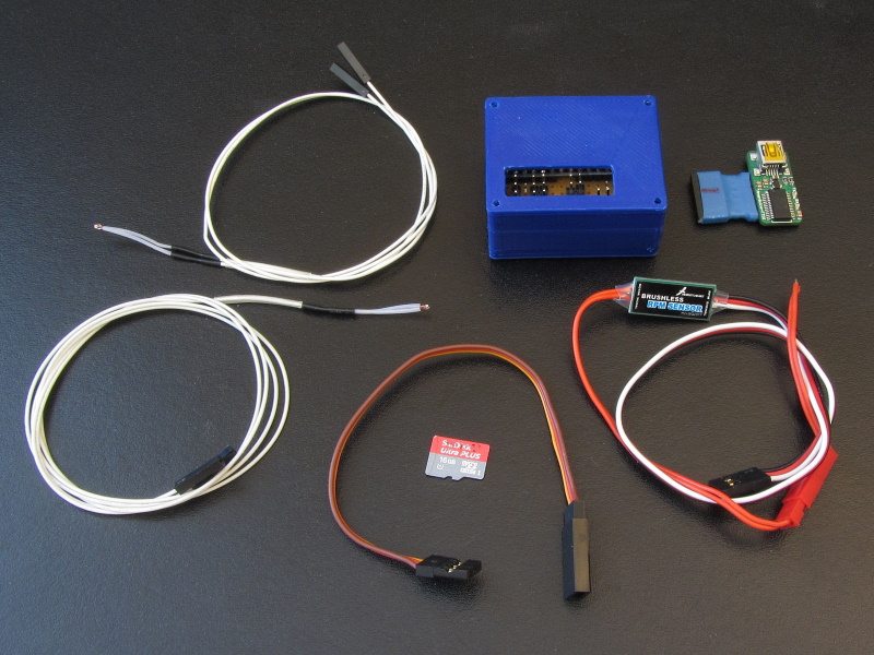
- RPM is captured using a Hobbywing RPM sensor which is the same as the Eagle Tree and Spektrum RPM sensors.
- RPM can be set using the TX while flying as either direct passthrough or regulated rpm.
- Temperature is captured using two glass bead NTC3950 thermistors commonly found on 3D printer set-ups.
- One temp sensor is epoxied onto the motor cross mount and the other is slipped under the ESC shrink cover on the heatsink side.
- One extra radio channel is needed to activate the passthrough/regulated functions.
Parts
The following are the parts used in the latest version of this tool-
- 1. Arduino 5v/16mhz Pro Mini Board
- 2. Omron 5v SPDT Signal Relay
- 3. Hobbywing RPM Sensor
- 4. NTC3950 Thermistors
- 5. Pin headers
- 6. Double Sided Prototyping PCB
- 7. 2x 100k Ohm, 1/4 watt resistors
- 8. 2x 10nF (103) capacitors
Part descriptions
Arduino Pro Mini - I wanted a small board with enough IO to handle all the tasks. The Pro Mini or the Arduino Nano both easily fit the bill as does the Teensy LC board. The Pro Mini was fianlly selected because it works and I can find them for around $5 each.
Omron Relay - After trying many different software attempts to create a smooth passthrough mode for the signal from the flight controller directly to the ESC, I finally decided to use the normally closed side of a relay to accomplish this task. There are two reasons for this-
- 1. If the board fails for some reason the relay will close to direct passthrough making it possible to continue flying the plane.
- 2. Having a direct, hard wired passthrough makes it completely smooth which is important in how the regulated section of the software works.
- 3. Inexpensive ($1.79)
Hobbywing RPM Sensor - I actually started with an early Eagle Tree unit that had an issue with how the power wires were from the factor - Black = Positive, Red = Negative. While looking for a replacement I found the HobbyWing version which according to my O-scope produce the same output. Bonus is they are less than a quarter of the price of the Eagle Tree units ($4.49)
NTC3950 Thermistors - I seleected this type of temp sensor because I had them already and they are really inexpensive ($1.40 ea). Also they are very easy to attach to the motor and ESC because of their size.
All together then, the parts for a single build cost me ~$18 plus any shipping.
Schematic
The schematic for this build can be seen here-
| 900px |
Board Build
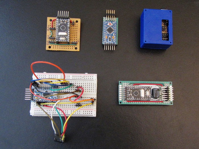
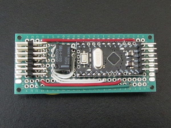
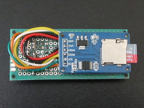
Here are some images of the first few versions and close-ups of the latest build-
| 800px |
| Some of the proto set-ups |

|
| First flight set-up |

|
| Current board (top) |

|
| Current board (bottom) |