Geared Aerodynamic Pan and Tilt
Contents |
|
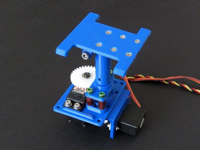
| Aerodynamic and Accurate! |
Introduction
Having designed and released a pile of different Pan and Tilt units I decided to try and make some improvements. I came up with a list of simple design goals that were based on requests and experiences with my and other PnT's. The list then, in order of importance is:
- Lighter and Faster than my HD Pan and tilt (100g)
- - New weight is 80g with the selected components
- Is smooth and precise with excellent centering
- - With a new programmable digital Hitec HS-5245MG servo, it is extremely smooth and centers beautifully
- Is more aerodynamic
- - Now with both servos mounted below the deck, it is very aerodynamic
- Can be made from off-the-shelf components
- - All but one component is made from standard off-the-shelf parts (see text)
- Rotates 360° or more
- - Rotation can be programmed from 236° to 398°
- Tilts down 50 degrees or more
- - Tilts down 42° (see text)
NOTE Apologies to all followers in Europe and Australia! The components selected started with a new (awesome) drive gear from ServoCity.com which I know can be very hard to find outside the US. The drive gear comes with the Hitec spline already molded in which made the design and subsequent build much easier. Of course this also means the gear shaft and bearings are also imperial dimensions.
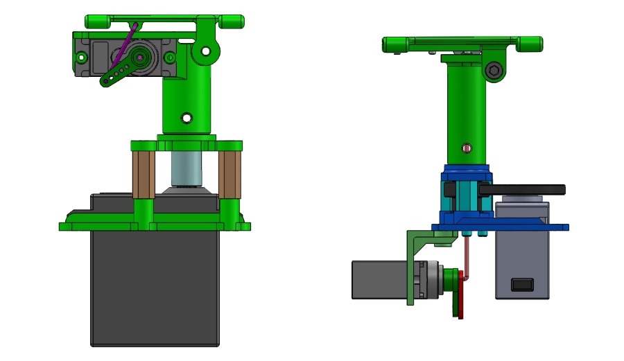
The new unit has a lower profile than the HD unit and needs a smaller through-deck hole:
|
| HD and Aerodynamic Pan and Tilts |
Configurations
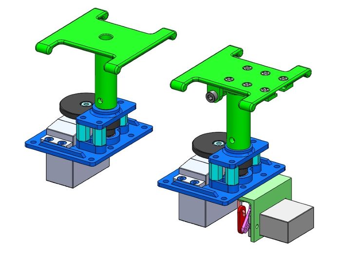
For this project I decided to keep it simple so there is only one pan-only setup and one tilt setup.
|
| Tilt and Pan-only decks |
Notes on Standard Configuration
- TBA
Parts and Specifications
Print Parts
- Base Plate
- Bearing Support Plate
- Tilt Servo Mount Bracket
- Tilt Turret
- Tilt Deck
- Tilt Deck Slide Covers
- Pan Deck
Off the Shelf Parts
- 2x Dubro #107 1/2A Control Horns (one pair)
- 1x Dubro #109 2-56 Spring Steel Kwik-Link Clevis
- 1x Dubro #172 2-56 Threaded Rod
- 1x Pushrod Linkage Stopper D2.1mm
- 1x ServoCity #RSA32-2HS-26 32 pitch/26 tooth Acetyl Servo Gear - C1 Spline
- 1x ServoCity #SPBD32-34-16 32 pitch/16 tooth Acetyl Plain Bore Gear
- 2x ServoCity #535018 .250"ID x .375"OD x .125"L Non-Flanged Ball Bearing w/Dual Shield
Hardware
- 4x M2.5x6mm Machine screws
- 4x M2.5 Flat Washers
- 8x M3 x 6mm Machine Screws
- 3x M3 x 10mm Aluminum Stand-off
- 1x M3 x 30mm Machine Screw
- 1x M3 Nylok Nut
- 2x M2 x 8mm Machine Screw
- 2X M2 Hex Nut
- 2x M2 x 4mm Machine Screw
- 6x M2 x 5mm Flat Head Machine Screw
- 1x M2 Flat Washer
Servos
- Pan - Hitec HS-5245MG digital programmable Mini Servo (27g)
- Tilt - Corona DS929MG digital micro servo
- NOTE: This project was designed specifically around the two servos shown
Mechanical Specifications
- Total weight with all hardware shown - 89 grams
- Pan rotaion - 236 - 398 degrees
- Tilt range - 0-42 degrees (down)
Parts Preparation
On any 3D print project, part preparation is key to a successful completion. The following images show what work needs to be done for this success.
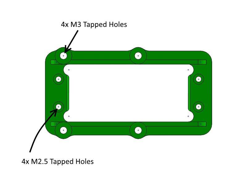
Servo Plate/Lower Deck Mount
The servo mount needs 4 holes tapped to M3 and 4 holes tapped to M2.5:
|
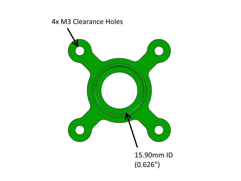
Bearing Plate/Upper Deck Mount
The assumption is your printer (or service) will hold the tolerance designed on an inside diameter. If your printer adds too much material you will need to make adjustments to accommodate the bearing OD which should push in with a little resistance:
|
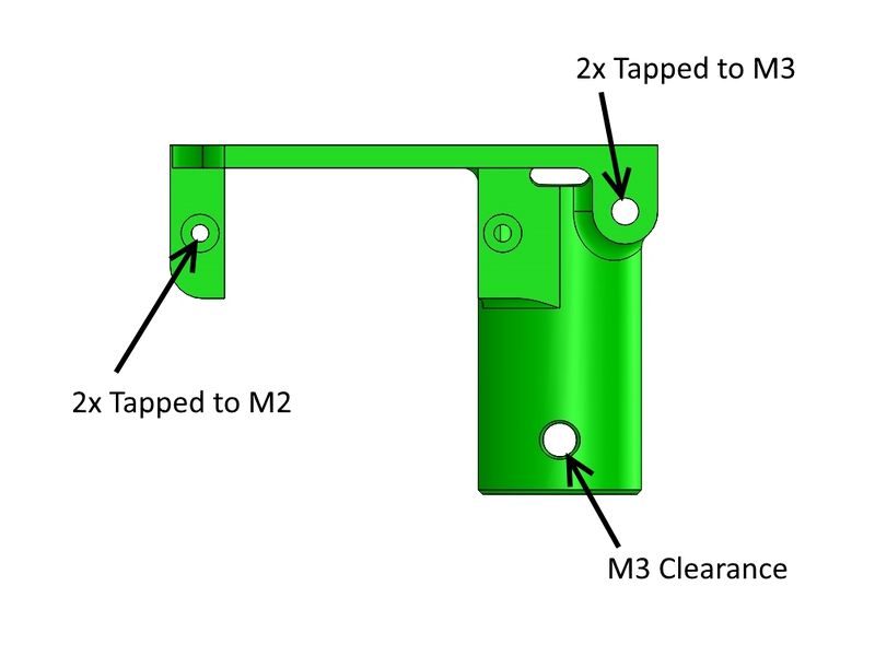
Turret Base
The Turret needs 2 holes tapped to M3 and 2 holes tapped to M2:
|
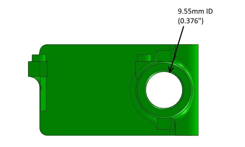
Like the bearing plate, the assumption is your printer (or service) will hold the tolerance designed on an inside diameter. If your printer adds too much material you will need to make adjustments to accommodate the coupler OD (0.375") which should push in with a little resistance:
|
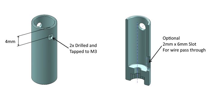
Servo Coupler
The Servo Coupler needs 2 holes drilled and tapped to M3. Optionally you can cut a 2mm x 6mm slot to pass wires from the camera plate down below the bearing plate.:
|
Assembly
On the Camera Mount pivot use the two Nylon M3 screws cut down so that they tighten against each other without jamming the pivot points.
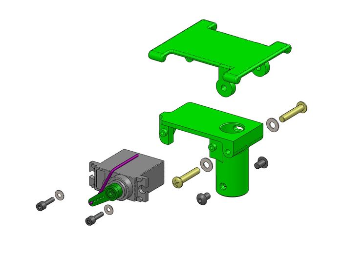
|
| Upper unit assembly |
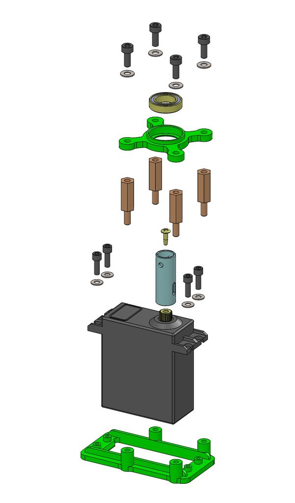
|
| Lower unit assembly |
A Video Sample
|
Test at Eldorado Dry Lake - October 2016 |
See Also
Project 3D Print Files
The following are the 3D print ZIP files used in this specific build. For more versions and information, please see my Thingiverse postings here:
Mark_q Thingiverse Designs
Where to buy the parts
- For the bearing and servo coupler -
- For the GWS S125-1t 25t servo -
- Global - GWS S125-1t Servo
Comments? Questions?