Difference between revisions of "DIY - Battery Pack Spot Welder"
(→Version 2 - Adding a Timer) |
|||
| Line 192: | Line 192: | ||
In this version 2 mod, I replace the bang-bang switch in version 1 with an Arduino controlled timer using a thumb activated switch on the handle to fire the solenoid. The code I have written allows adjustment from 20ms - 600ms and has a delay function built in so it will only fire the solenoid once each time you press the trigger.<br><br> | In this version 2 mod, I replace the bang-bang switch in version 1 with an Arduino controlled timer using a thumb activated switch on the handle to fire the solenoid. The code I have written allows adjustment from 20ms - 600ms and has a delay function built in so it will only fire the solenoid once each time you press the trigger.<br><br> | ||
| − | You must already have some understanding of electronics, Arduino boards and their set-up. Please see the <u>[https://www.arduino.cc/ Arduino]</u> website for more information. | + | '''Note 1:''' I am not an Arduino or micro-controller guru! This is simply my version and I am sure someone will be able to improve on it.<br><br> |
| + | |||
| + | '''Note 2:''' You must already have some understanding of electronics, Arduino boards and their set-up. Please see the <u>[https://www.arduino.cc/ Arduino]</u> website for more information. | ||
<br><br> | <br><br> | ||
| − | '''NOTE: While this approach should yield more consistent welds, the results are very dependent on the quality of the components and the builders skill. There are still safety concerns because with the use of an electric solenoid (relay) there can be issues with sticking contacts and the effect of temperature on the contact mechanism.''' | + | '''NOTE: While this approach should yield more consistent welds, the results are very dependent on the quality of the components and the builders skill. There are still safety concerns because with the use of an electric starter solenoid (relay) there can be issues with sticking contacts and the effect of temperature on the contact mechanism.''' |
<br> | <br> | ||
Revision as of 13:39, 13 February 2019
|
Introduction
This article covers three versions of my spot welder build. Version 1, the Bang-Bang welder, is based on an excellent write-up on RC Groups by poster Mochanic. In use, it worked flawlessly for me.
Version 2, The Welder Timer, is basically the same as version 1 with an electronic timer to replace the bang-bang switch and bring more consistency to the weld quality.
Version 3, The JP Welder, is a more professional approach and was found in a blog dedicated to building battery packs for electric bikes. You can (and should) read more about this here - JP Spot Welder
Version 1 - Bang-Bang
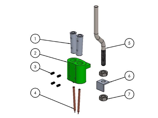
The parts for this V1 build are shown and listed below. The hardware bits are all in imperial measures as this was easiest for me to source and much of it I already had.
|
| Weld head parts |
Weld Head Parts
- 2x - Aluminum Tube, bar stock, 3/8" x 1-1/4"
- 1x - 3D printed Weld Head (STL below)
- 4x - 4-40 x 1/4" set screws
- 2x - Solid Copper nails, .120" x 1.25"
- 1x - Handle bar, 1/4"-20 x 4" bolt
- 1x - 1/16" x 1/2" x 1/2" x 5/8"L Aluminum Angle
- 2x - 1/4-20 Hex Nut
- 1x - 1/4" Bit Driver handle
Trigger Parts
- 1x - ATV Starter Solenoid
- 1x - Momentary Switch, N/O
- 1x - 6" 16ga wire
- 1x - 1-yard AWG8 Silicone Wire, Red
- 1x - 1-yard AWG8 Silicone Wire, Black
- 4x - AWG8 x 1/4"" Ring Connectors
- 4x - 3/8" x 1" Shrink Tube
- 1x - Garden Tractor battery
I found an inexpensive (~$4) screw bit driver at the local hardware store which provides the handle as the Handle Bar just slides inside where the bits normally go. I added two 4-40 screws to lock it in place.
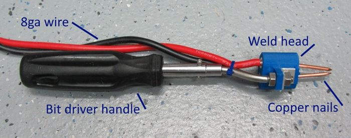
|
| Weld head/handle assembly |
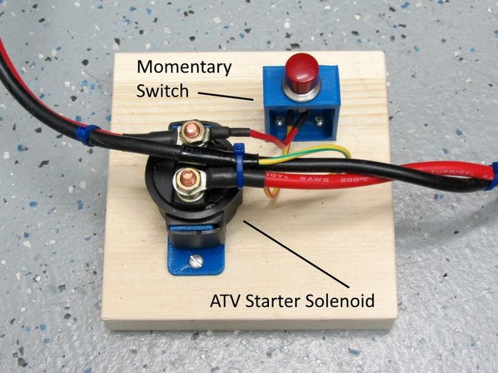
Wiring for the solenoid I selected.
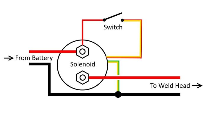
|
| Trigger assembly |
For the Trigger I printed a stand for the switch and a piece to hold the solenoid.
|
| Trigger assembly |

|
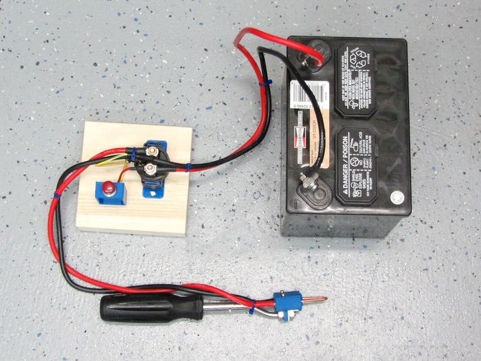
| Complete assembly, ready to weld! |
Getting it all together
Here are a few part details:
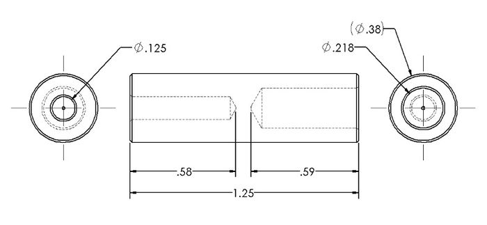
#1 Aluminum Tube
The two aluminum tubes are made from 3/8" Aluminum Roundbar. In my case I have a lathe which makes centering and drilling the holes very simple. Without a lathe a drill press can be used and the hole do'nt have to be perfectly centered. The drill sizes and depths are shown below.
|
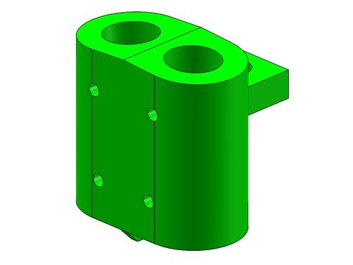
#2 Weld Head (Print)
This 3D part can be made in ABS or PLA. It should be printed with an infil of 70% or more. The two holes for the aluminum tubes are sized to be a firm fit. If the tubes don't push in you can clean the holes up with a 3/8" drill bit.
|
#4 Solid Copper Nails
These you can pick up on ebay. They are .120" in diameter and 1-1/4" long. Simply cut the nail heads off and clean up the cut before attaching to the head.
#6 Aluminum Angle
This piece is optional and is made from standard hardware store aluminum angle. The standard size is 1/16" x 1/2" x 1/2". The cut to length is 9/16" and the hole is 1/4" Dia.
Basic Assembly
- 1. Press the two aluminum tubes into the Weld-Head print making sure the large hole end is toward the top.
- 2. Using the four small holes as a drill guide, drill the four set-screw holes through the plastic and aluminum using a #43 drill bit.
- 3. Tap the four holes with a 4-40 tap.
- 4. Strip and tin the ends of the AWG-8 wire and plug them into the top of the weld head. Add the top two set screws and tighten.
- 5. Add the two copper nails to the bottom holes and tighten their set screws.
- 6. Add the handle bar, 2 - 1/4-20 nuts and the handle.
- 7. Assemble the switch and solenoid and add the battery.
V1 Setup and Use
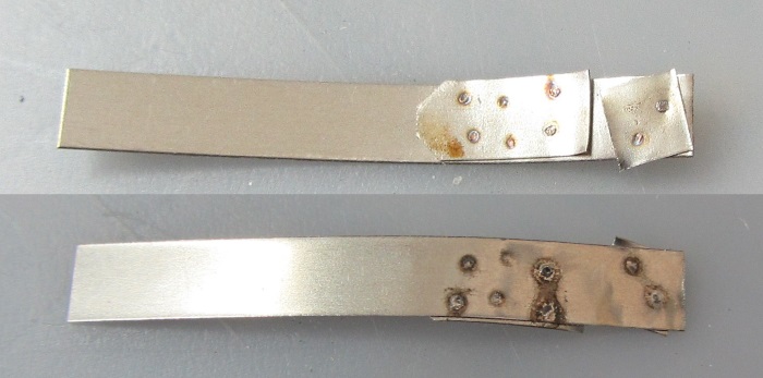
Practice, practice, practice!
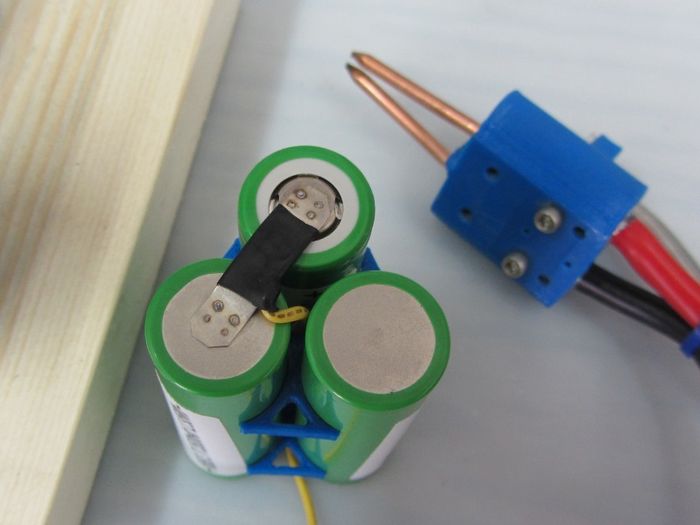
Using all the gear shown hear, this is one powerful spot welder! Be careful and practice until you have a method and technique which produces consistent quality spot welds. In my first initial tests, I literally blew holes through the nickel test strips. I finally found that simply banging the momentary switch was enough to produce a complete, solid weld.
|
| Practice! |
The method I use to hold the handle is to place the two copper nails at a 45 degree angle and gently press the tips down. Once the tips are positioned correctly and stable, I bang the momentary switch and instantly have a spot welded part.
|
Version 2 - Adding a Timer
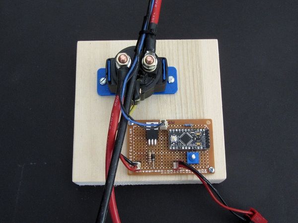
In this version 2 mod, I replace the bang-bang switch in version 1 with an Arduino controlled timer using a thumb activated switch on the handle to fire the solenoid. The code I have written allows adjustment from 20ms - 600ms and has a delay function built in so it will only fire the solenoid once each time you press the trigger.
Note 1: I am not an Arduino or micro-controller guru! This is simply my version and I am sure someone will be able to improve on it.
Note 2: You must already have some understanding of electronics, Arduino boards and their set-up. Please see the Arduino website for more information.
NOTE: While this approach should yield more consistent welds, the results are very dependent on the quality of the components and the builders skill. There are still safety concerns because with the use of an electric starter solenoid (relay) there can be issues with sticking contacts and the effect of temperature on the contact mechanism.
|
| Shown here without a cover, 5v regulator (under board) not shown |
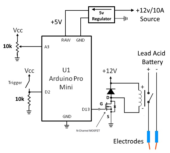
V2 schematic-
|
V2 timer parts list-
- 1x 10K Ohm, 1/4w resistor
- 1x 1K Ohm, 1/4w resistor
- 1x 10K Ohm Potentiometer
- 1x 1N4001 Diode
- 1x IRF540N Mosfet
- 1x Arduino Pro-Mini
- 1x 12v/5v, 200mAh Voltage Regulator
The Code-
Click on this link to download a txt file of the code I use - Weld Timer Code
V2 Setup and Use
As shown in the above schematic, the weld battery which in my case is a small garden tractor lead-acid, must remain separate from the battery or power source for the board and solenoid. Because I want the solenoid to act fast and consistently, I power the board and solenoid with a 3300mAh/3 cell lipo which can easily dump 10A at 12v.
Use is basically the same as version 1 with regards to how to position and hold the handle. Remember to test, test, test before actually welding a good cell. Start with a short time and two pieces of nickel strip. Turn the time up until you get good welds but not so high that you get any holes in the tin strips.
Version 3 - The JP Welder
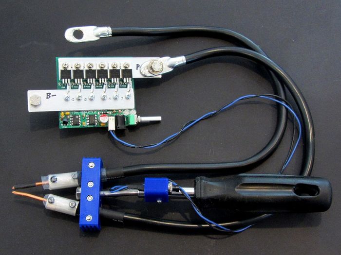
This version is based on the great work by Jakov Perisic on the endless-sphere Electric Vehicle Technology site. The posts where I found this can be linked to here - JP Spot Welder
|
| The PCB and handle setup (12v/2A wall-wart not shown) |
In my case I opted to buy just the PCB, Aluminum Strips and PIC controller for $40 then bought the rest of the board components from digi-key.com. This saved me a little money but cost me a little time. To that end, there is an excellent assembly manual put together by JP which can be found here - DIY Manual by JP
I made my electrode cables from 4ga battery cables I purchased from a local auto parts store ($9 for both). They are each 20" long and came with ring terminal ends already crimped. The electrode couplers were made on my mini lathe out of 1/2" aluminum bar stock and the electrodes themselves were (again) made from pure copper nails I bought on ebay.
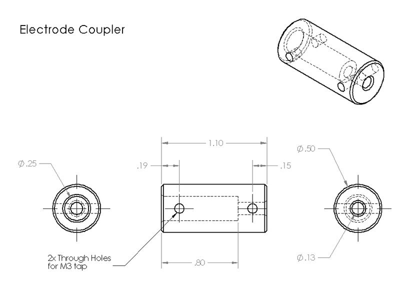
|
| Coupler drawing |
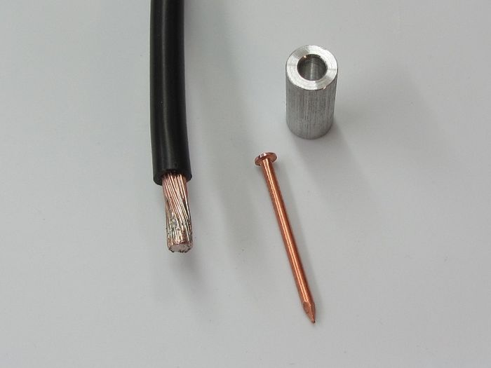
|
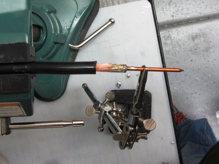
|
| Copius tinning and soldering |
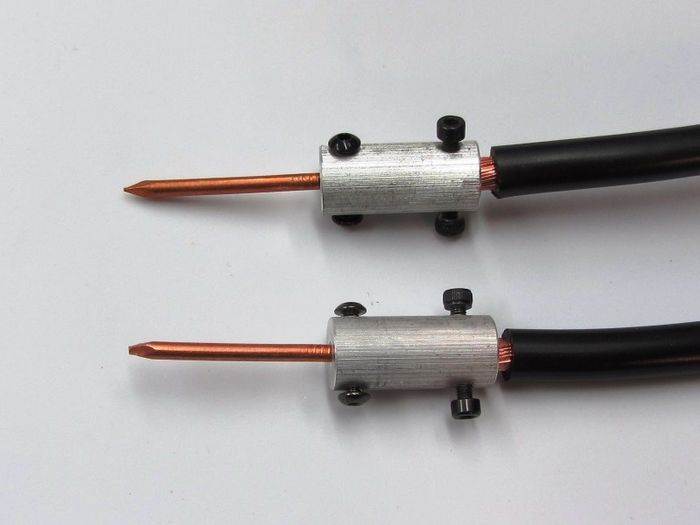
|
| Finished with M3 screws to secure the cable and electrodes |
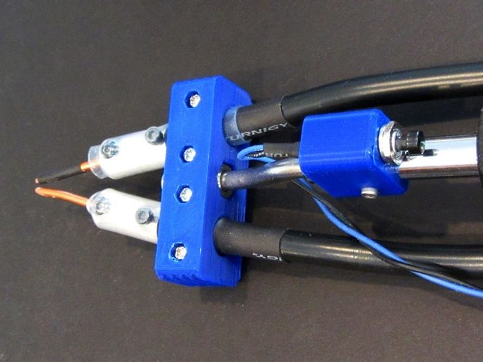
Next I designed and printed up a new "Weld Head" to clamp the cables and attach the handle/switch assembly.
|
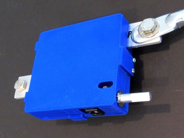
Last, I made a protective case to keep the PCB from being damaged.
|
Setup and Use
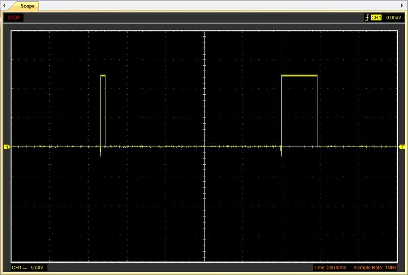
Handle position and use is the same as V1 & V2 as is testing and actual welding. The welds may appear smaller but the penetration should be as good or better than with v1 or v2. This is because the JP Welder is a much more precisely controlled "double hit" spot weld controller. An image of a scope view of the hits is shown below.
|
| Oscilliscope capture of the welder signal |
Print Files
Version 1
- 10039.STL Weld Solenoid Mount - v2r1
- 10040.STL Weld Solenoid Switch Mount - v1r2
- 10041.STL Welder Head - v2r3
Version 2
- 10039.STL Weld Solenoid Mount - v2r1
- 10041.STL Welder Head - v2r3
- 10042.STL Weld Timer Switch Mount - v1r1
- 10043.STL Weld Timer Cover - v1r1
Version 3
- 10042.STL Weld Timer Switch Mount - v1r1
- 52199.STL V3 Welder Head - v2r1
- 52200.STL Welder PCB Cover Lower - v1r1
- 52201.STL Welder PCB Cover Upper - v1r1
See Also
Comments? Questions?
