Difference between revisions of "Mini Talon Noses2"
(→Introduction) |
(→Introduction) |
||
| Line 18: | Line 18: | ||
<ads media=BG1 /> | <ads media=BG1 /> | ||
| − | |||
| − | |||
| − | |||
| − | |||
<br><br> | <br><br> | ||
Revision as of 18:02, 9 April 2017
June, 2016
| |
| Ready for printing! |
Introduction
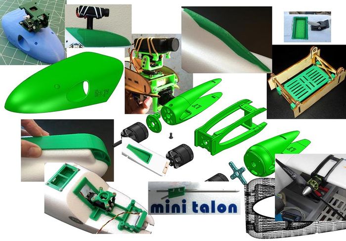
This article is a collection of 3D print parts specifically designed to fit the X-UAV Mini Talon. These have all been printed and most have been flight tested and even a few - crash tested :).
Many of the parts found here are also on my Thingiverse pages although since all parts are published here first, this is where you will find the most current versions. As on Thingiverse, everything found here is protected by Copyright and licensed under the terms of the Creative Commons "Attribution-NonCommercial-ShareAlike 4.0 International" license.
Enjoy - Mark
<ads media=BG1 />
Canopy's and Set-ups
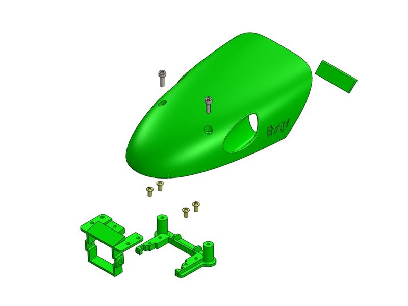
I have redone the feature set that makes up this 3D model smoothing out the surface and profile and changing the NACA style vent to side air scoop type vents. It prints more cleanly now and I have added a version which will support either the Geared Pan & Tilt or the 390deg Pan & Tilt. Below you will find the latest versions of this fun design with downloads for all the printable STL files.
Plain Canopy
If you want to simply cover the nose for a more appealing look or need something to fit to your own structure this may be the part you want. The two FPV camera mounts are optional.
|
| Image | Part Number | Part Description | Print File |
|
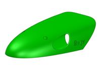
47001 | Canopy, Plain | 47001.STL |
|
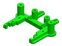
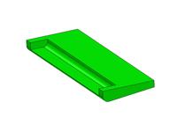
52001 | Canopy support, front | 52001.STL |
|
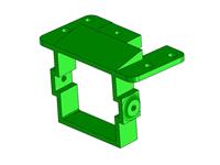
52002 | Canopy support, rear | 52002.STL |
|
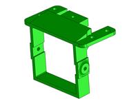
52004 | Optional HS1177 Camera Mount | 52004.STL |
|
52005 | Optional HS1184 Camera Mount | 52005.STL |
Hardware Shown
| Quantity | Part Description |
| 4x | Philips head machine screw, M3 x 8mm, Nylon |
| 2x | Socket head cap screw, M3 x 10mm, Steel |
Install
- Use E6000, Beacons FoamTac or UHU-POR glue to fasten front support and rear catch in place.
Print Recomendations
- ABS is recommended for this part. It will fit and work fine on 0.2mm resolution and slow to moderate print speed.
Static Camera Mounts
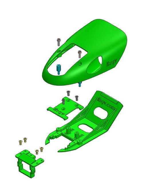
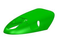
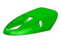
This version has a cut-out and platform for the Mobius style HD cams and is the most aerodynamic of all the camera mount units. There are two different canopies, one specifically for the Mobius Mini and one which will accomodate either the Mobius or Runcam cameras.
|
| Image | Part Number | Part Description | Print File |
|
47003 | Canopy, Mobius Mini | 47003.STL |
|
47005 | Canopy, Mobius/Runcam | 47005.STL |
|
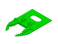
54002 | Front deck plate, narrow | 54002.STL |
|
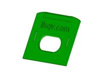
54001 | Rear deck plate, narrow | 54001.STL |

|
52006 | Deck plate support rib | 52006.STL |
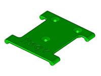
|
52007 | HD camera mount plate | 52007.STL |

|
52004 | Optional HS1177 Camera Mount | 52004.STL |

|
52005 | Optional HS1184 Camera Mount | 52005.STL |
Hardware Shown
| Quantity | Part Description |
| 4x | Philips head machine screw, M3 x 8mm, Nylon |
| 2x | Socket head cap screw, M3 x 10mm, Steel |
| 2x | Standoff, M3 x 10mm, Nylon |
| 3x | Flathead machine screw, M3 x 10mm, Steel |
Install
- Use E6000, Beacons FoamTac or UHU-POR glue to fasten front and rear decks and ribs in place.
Print Recomendations
- ABS is recommended for this part. It will fit and work fine on 0.2mm resolution and slow to moderate print speed.
Brushless Roll Attachment
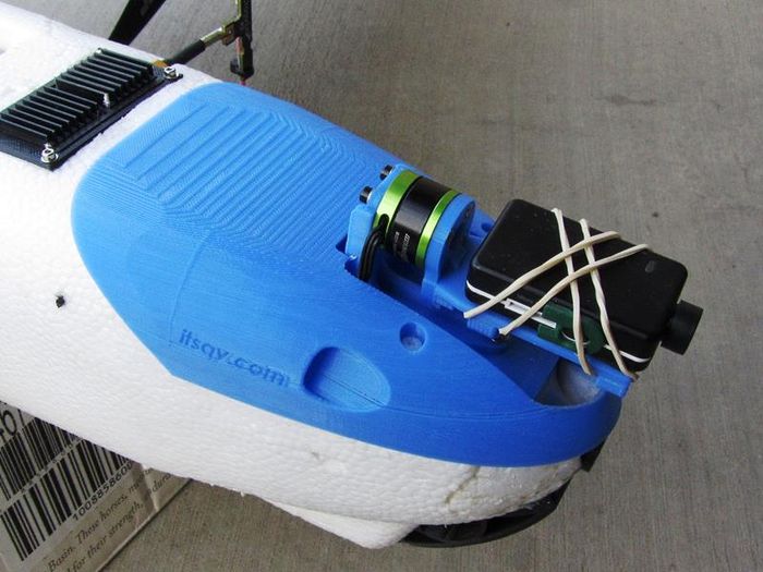
This is a new addition to the line-up. The canopy has an extra large cut-out so that a brushless gimbal roll attachment can be utilized with some protection for additional electronics like controller, cam switch, etc. The version shown here uses a small 22mm OD motor, a Multistar 1807/340kv.
|
| Roll attachment shown with an early prototype canopy and the Mobius Mini |
This really is designed for the Mobius Mini but a larger camera could be used with a slightly larger Gimbal motor such as a 2208-80t/90kv unit. Some canopy trimming may have to be done if an alternate motor is used.
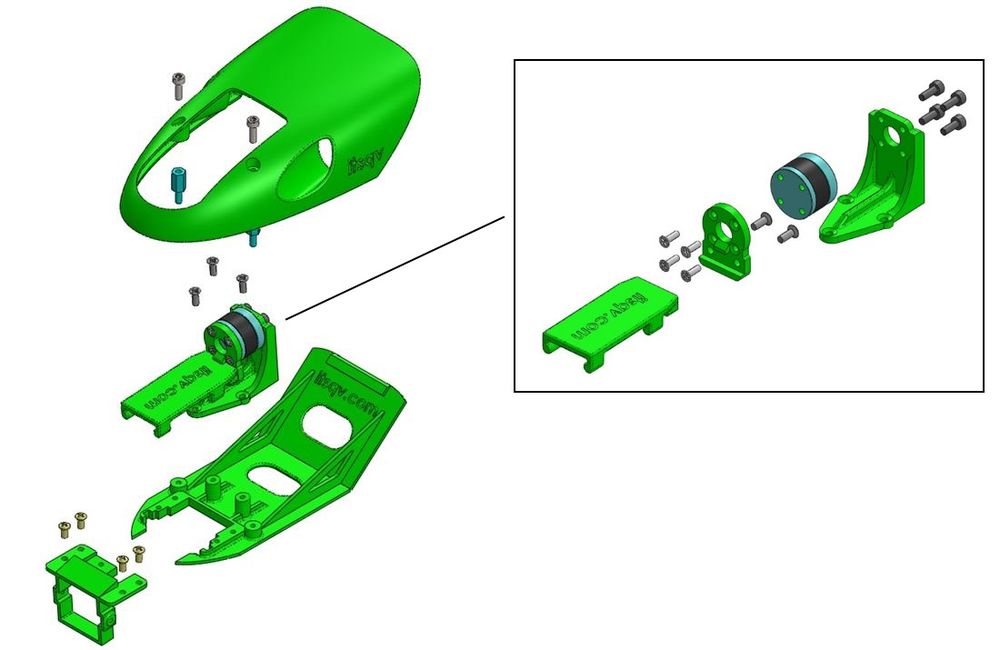
|
| Image | Part Number | Part Description | Print File |
|
47013 | Canopy, Roll attachment | 47013.STL |

|
54002 | Front deck plate | 54002.STL |

|
54001 | Rear deck plate | 54001.STL |

|
52006 | Canopy support, rib | 52006.STL |
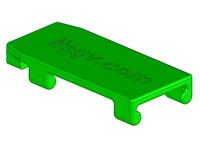
|
52011 | Roll attachment camera plate | 52011.STL |

|
52013 | Roll attachment end plate | 52013.STL |
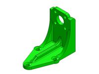
|
52012 | Roll attachment motor stand | 52012.STL |

|
52004 | Optional HS1177 Camera Mount | 52004.STL |

|
52005 | Optional HS1184 Camera Mount | 52005.STL |
Hardware Shown
| Quantity | Part Description |
| 4x | Philips head machine screw, M3 x 8mm, Nylon |
| 2x | Socket head cap screw, M3 x 10mm, Steel |
| 2x | Standoff, M3 x 10mm, Nylon |
| 5x | Flathead machine screw, M3 x 10mm, Steel |
| 4x | Flathead machine screw, M2.5 x 6mm, Steel |
| 4x | Socket head cap screw, M2.5 x 6mm, Steel |
Install
- Use E6000, Beacons FoamTac or UHU-POR glue to fasten front and rear decks and ribs in place.
Print Recomendations
- ABS is recommended for this part. It will fit and work fine on 0.2mm resolution and slow to moderate print speed.
Light Weight Pan and Tilts
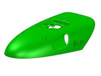
This is also a new release. Both the "Lightweight Pan and Tilt" and the "Lightweight Pan and Tilt - v2" I have published on Thingiverse will bolt directly to the canopy.
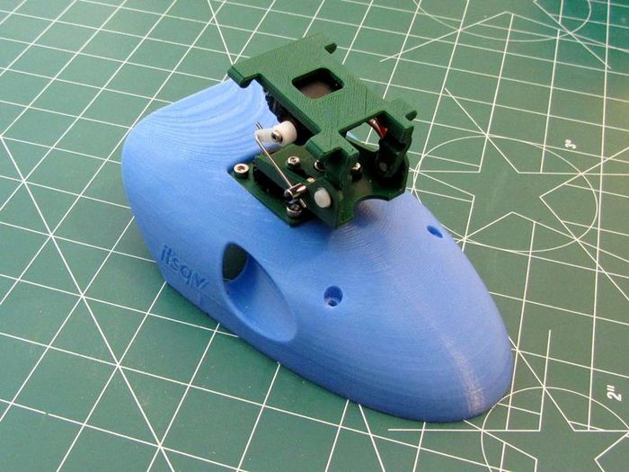
|
For more information on these two add-ons please see the Thingiverse pages here:
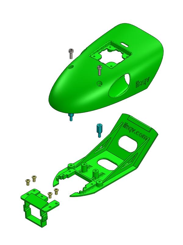
|
| Image | Part Number | Part Description | Print File |
|
47009 | Canopy, Lightweight Pan and Tilt | 47009.STL |

|
54002 | Front deck plate | 54002.STL |

|
54001 | Rear deck plate | 54001.STL |

|
52006 | Deck Plate, rib | 52006.STL |

|
52004 | Optional HS1177 Camera Mount | 52004.STL |

|
52005 | Optional HS1184 Camera Mount | 52005.STL |
Hardware Shown
| Quantity | Part Description |
| 4x | Philips head machine screw, M3 x 8mm, Nylon |
| 2x | Socket head cap screw, M3 x 10mm, Steel |
| 2x | Standoff, M3 x 10mm, Nylon |
Install
- Use E6000, Beacons FoamTac or UHU-POR glue to fasten front and rear decks and ribs in place.
Print Recomendations
- ABS is recommended for this part. It will fit and work fine on 0.2mm resolution and slow to moderate print speed.
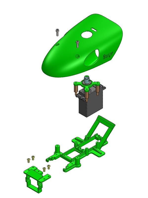
Heavy Duty Pan and Tilt
This is the same set-up as previously released but with the new canopy and FPV camera mounts which lower the cameras enough to clear the bottom edge of the canopy. For more information on the P&T parts and hardware please see the P&T article here - Heavy Duty Pan and Tilt
|
| Image | Part Number | Part Description | Print File |
|
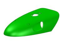
47007 | Canopy, Heavy Duty Pan and Tilt | 47007.STL |
|
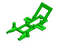
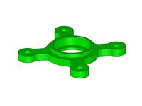
54003 | GWS Servo mount | 54003.STL |
|
2205 | GWS Servo bearing plate | 2205.STL |

|
52004 | Optional HS1177 Camera Mount | 52004.STL |

|
52005 | Optional HS1184 Camera Mount | 52005.STL |
Hardware Shown
| Quantity | Part Description |
| 4x | Philips head machine screw, M3 x 8mm, Nylon |
| 2x | Socket head cap screw, M3 x 10mm, Steel |
Install
- Use E6000, Beacons FoamTac or UHU-POR glue to fasten front and rear decks and ribs in place.
Print Recomendations
- ABS is recommended for this part. It will fit and work fine on 0.2mm resolution and slow to moderate print speed.
Plain Decks
This section has a few "Plain" decks. These are generally not compatible with any of the canopies and are full coverage decks which cover all the foam on the front of the fuselage.
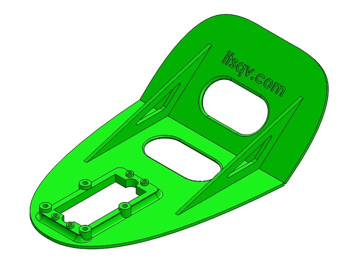
Simple GWS Servo Deck
If all you need is a simple deck to mount the GWS S125-1T, 360 degree servo, this is it. This deck puts the servo forward so a Pan and Tilt can look straight down over the nose. Additionally, if you want to add the heavy duty bearing plate and servo coupler, the bosses are here and ready to be tapped to M3 for the bearing plate stand-offs.
NOTE: This is a full coverage deck and is not compatible with any of the canopies.
|
| Image | Part Number | Part Description | Print File |
|
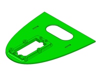
54005 | Front deck plate, wide, GWS | 54005.STL |
|
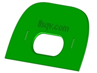
54006 | Rear deck plate, wide | 54006.STL |

|
52006 | Deck plate support rib | 52006.STL |
Install
- Use E6000, Beacons FoamTac or UHU-POR glue to fasten front and rear decks and ribs in place.
Print Recomendations
- ABS is recommended for this part. It will fit and work fine on 0.2mm resolution and slow to moderate print speed.
Skid Plates
Front Skids
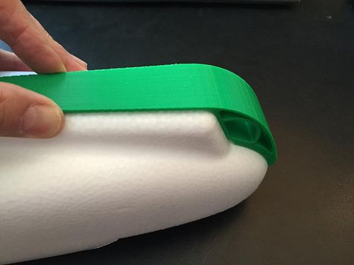
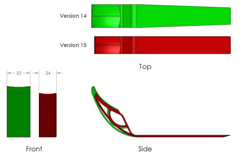
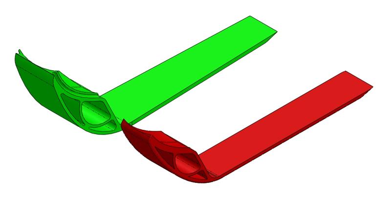
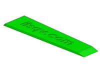
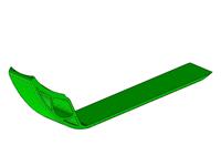
If you want the best fore and aft skid protection then look no further! These skids have been tested 100's of times on some of the worst landing surfaces you could imagine and they do the job. There are two versions of the front skid, one wide, one narrow. The wide, 2 piece, skid does a better job in cut shale or other super abrasive surfaces, the narrow version is lighter and printable as a single piece.
|
|
|
| Image | Part Number | Part Description | Print File |
|
52101 | Front skid, nose piece | 52101.STL |
|
52102 | Front skid, flat piece | 52102.STL |
|
52103 | Front skid, 1 piece narrow | 52103.STL |
Rear Skid
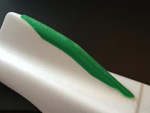
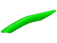
This skid does an amazing job of keeping the rear lower fin intact and straight.
|
| Image | Part Number | Part Description | Print File |
|
52104 | Rear skid | 52104.STL |
Install
- Use E6000, Beacons FoamTac or UHU-POR glue to fasten skid pieces in place.
Print Recomendations
- ABS is recommended for these parts. They will fit and work excellently on 0.2mm resolution and slow to moderate print speed. The rear skid can be printed right-side up or down, both with supports. It will look best printed down-side up but this is difficult to print for some.
Gear Decks
Below are two gear decks for mounting electronics in the fuselage. The first "Main Gear Deck" bolts into the center structure and is a great place to mount a flight controller and other bits. The second "Rear Gear Deck" sits just behind the wood center structure and is a great place to mount an RX, GPS puck or ESC.
Main Gear Deck
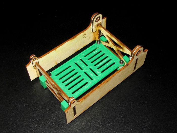
Having a bolt-in gear deck is a really nice feature in any build. Many have re-designed the entire wood structure but I find this to be redundant, unnecessary work as the wood structure is quite good, stronger than PLA or ABS of the same dimensions and very easy to work with.
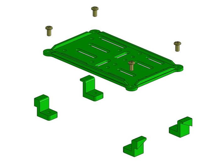
This gear deck then uses four threaded clips which glue nicely to the wood structure and put the deck just above the bottom of the structure. You could also elect to use four rubber dampers if you are having vibration issues. The first picture below is an older version of this deck which can be found on Thingiverse if you think it will better suit your needs.
|
| Older version with outside deck clips |
|
| Image | Part Number | Part Description | Print File |
|
52017 | Gear deck | 52017.STL |
|
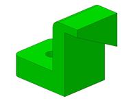
52015 | Gear deck clip 'A' | 52015.STL |
|
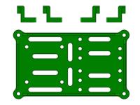
52016 | Gear deck clip 'B' | 52016.STL |
|
1021STL | Complete STL group | 1021STL.STL |
Install
- 1. Print the "Complete STL group" file
- 2. Tap the four clips to M3
- 3. Assemble the deck in the wood structure using four M3 machine screws AFTER the wood structure is installed in the plane
- 4. Make sure all four clips are lined up evenly and fully seated against the wood
- 5. Use thin CA to secure the clips to the wood being careful not to glue the deck to the clips
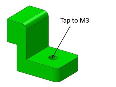
|
Print Recomendations
- ABS or PLA is recommended for this part. It will fit and work fine on 0.2mm resolution and slow to moderate print speed.
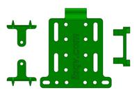
Rear Gear Deck
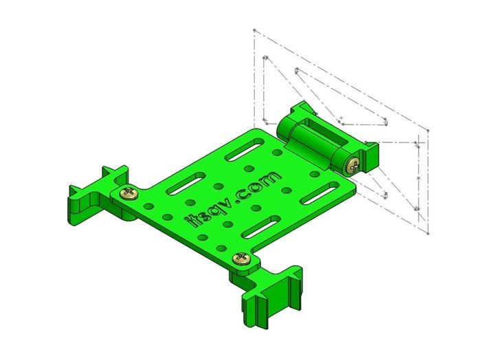
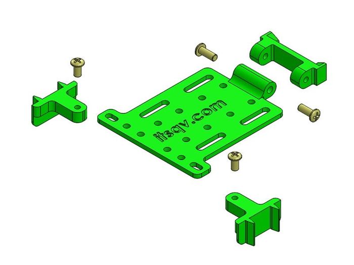
The rear deck idea came from a poster on RCGroups as a way to mount an ESC directly under an air vent in the hatch. I really liked this idea so came up with my own version which pivots up so you can get to anything below the deck if and when needed.
|
|
| Image | Part Number | Part Description | Print File |
|
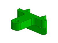
52018 | Deck pivot mount | 52018.STL |
|
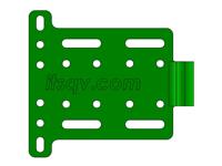
52019 | Rear deck plate | 52019.STL |
|
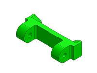
52020 | Rear deck mount hold-down | 52020.STL |
|
52021STL | Complete rear deck STL group | 52021STL.STL |
Install
- 1. Print the "Complete STL group" file or the individual parts
- 2. Tap the the two pivot ears to M3
- 3. Tap the two rear mounts to M3
- 4. Mount the deck to the pivot piece with two M3 x 8mm screws (I use nylon screws)
- 5. Snap the pivot piece into the center of the rear wood cross-piece
- 6. Wick in some thin CA glue
- 7. Pivot the deck to level and mark the side foam where the rear mounts are to go
- 8. Use E6000 or UHU-POR glue to glue the mounts in place and screw the deck down to hold it all together while the glue sets
Print Recomendations
- ABS or PLA is recommended for this part. It will fit and work fine on 0.2mm resolution and slow to moderate print speed.
Motor Mounts
Rear Motor Mount
In my opinion the wood mount is sufficiently strong and when set-up correctly will provide secure mounting and enough air flow for cooling. Please see my set-up of the wood mount for more information - Wood mount set-up.
Having said that, I designed this print to acommodate all the aspects of the correctly set-up wood mount as an alternative for those that want to do a print instead. This mount has a larger center hole and wire pass through as well as 5mm stand-offs to allow more cooling air to exit the fuselage. Also in this design are four "ears" that lock it into position and two sets of cross mount holes on 34mm & 44mm bolt circles to accomodate many 22XX and 28XX motors. The mount holes have "nut wells" to glue in M3 nuts on the forward side.
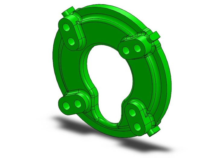
|
| Rear view |
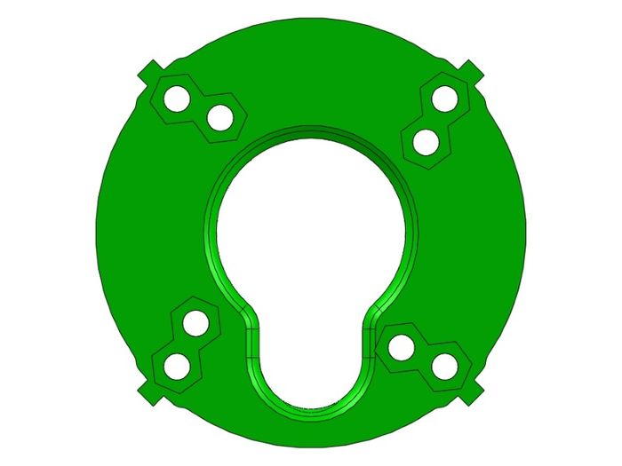
|
| Front view |
| Image | Part Number | Part Description | Print File |

|
52022 | Motor mount | 52022.STL |
Install
- 1. Print the mount front side down
- 2. Clean-up the print and with a little glue, push four M3 nuts into the nut wells which fit your cross mount
- 3. Put small pieces of cellophane tape over each nut to protect it from the mount glue
- 4. Using a soldering iron or hot wire, carve out the four small notches for the mount ears in the fuselage halves
- 5. Dry fit the part insuring the fuselage halves go together tightly
- 6. Use E6000, Beacons FoamTac or UHU-POR glue to glue the mount in place
- 7. After the fuse is glued up, use a small hotwire through each cross-mount hole to pierce the cellophane tape and open the foam up
Print Recomendations
- ABS is recommended for this part with an infill of at least 60%. It will fit and work fine on 0.2mm resolution and slow to moderate print speed.
Original Twin Motor Mounts
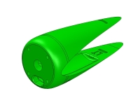
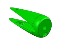
The twin project was another that came from some discussion on RCGroups. I did this one a little differently because I did the design and then left it up to the community to do some of the initial testing. The results were mixed with some folks having launch issues and some having no problems.
After a few weeks of this someone requested simple 2D drawings of something they could cut out of plywood or plastic so I came up with the "Simple" solution. This uses simple 6 piece skeleton mounts that are assembled then mounted to the plane. Thee are the mounts I eventually (successfully) tested with and they are nearly identical to the "swoopier" mounts first designed.
This then are these two versions starting with the original design.
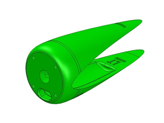
|
| Left side mount |
| Image | Part Number | Part Description | Print File |
|
52008 | Motor mount, left side | 52008.STL |
|
52009 | Motor mount, right side | 52009.STL |
|
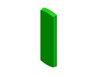
52010 | Motor mount key | 52010.STL |
Install
- 1. Print the mount motor face down
- 2. Clean up and push, with a little glue, four nyloc nuts into the nut wells inside the mount
- 3. Carefully measure and mark where the inside edge of the mount is to go
- 4. Make a trough in the wing foam to pass ESC motor wires into where the mount will be
- 5. Apply liberal amounts of glue and push the mount into position on the wing
- 6. Make sure to thread the ESC wires in through the wire hole in the mount face
- 7. Check that the mounts are perfectly parallel with a straight edge then clamp and pin in place and let the glue fully set
Print Recomendations
- ABS is recommended for this part with an infill of at least 40%. It will fit and work fine on 0.2mm resolution and slow to moderate print speed.
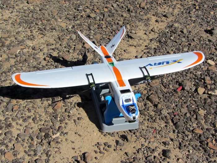
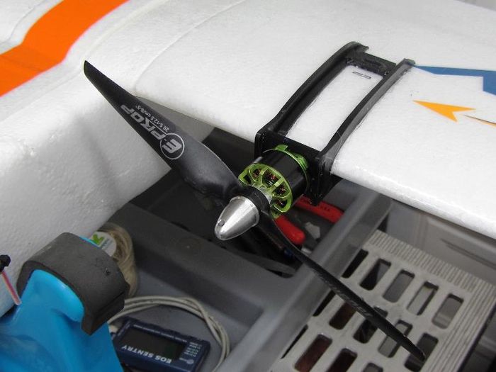
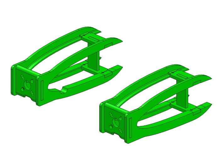
Simple Twin Motor Mounts
Here are the simpler, easier to print mounts. They aren't much to look at but they are effective!
|
| MT2 with Twins! |
|
|
| Image | Part Number | Part Description | Print File |
|
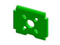
52023 | Simple_motor mount, front | 52023.STL |
|
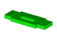
52024 | Simple_motor mount, gusset | 52024.STL |
|
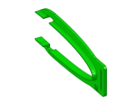
52025 | Simple_motor mount, key | 52025.STL |
|
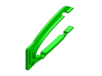
52026 | Simple_motor mount, LL side | 52026.STL |
|
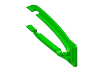
52027 | Simple_motor mount, LR Side | 52027.STL |
|
52028 | Simple_motor mount, RL side | 52028.STL |
|
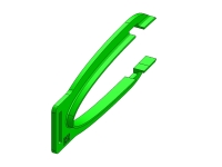
52029 | Simple_motor mount, RR side | 52029.STL |
Install
- 1. Print the 12 mount pieces in ABS
- 2. Clean up and assemble the two sides with ABS pipe cement being careful to get the right pairs together. A dry fit will help keep it straight.
- 3. Carefully measure and mark where the inside edge of each mount is to go
- 4. Make a trough in the wing foam to pass ESC motor wires into where the mount will be
- 5. Apply liberal amounts of glue and push the mount into position on the wing
- 6. Check that the mounts are perfectly parallel with a straight edge then clamp and pin in place and let the glue fully set
Print Recomendations
- ABS is recommended for this part with an infill of at least 40%. It will fit and work fine on 0.2mm resolution and slow to moderate print speed.
Misc Mini Talon Parts
TBA
See Also
TBA
Comments? Questions?