Difference between revisions of "Maker Select 3D Printer Improvements"
(→Parts) |
(→More Mods) |
||
| (3 intermediate revisions by the same user not shown) | |||
| Line 419: | Line 419: | ||
| − | == More Mods == | + | == More Mods! == |
Of course the mods never stop! | Of course the mods never stop! | ||
<br> | <br> | ||
| − | One issue I kept finding was a small amount of chatter on the Y axis. After much tuning and set up changes I decided to convert to a Bowden feed system which takes the motor and pinch roller assembly off the X-axis carriage. This makes the | + | One issue I kept finding was a small amount of chatter on the Y axis. After much tuning and set up changes I decided to convert to a Bowden feed system which takes the motor and pinch roller assembly off the X-axis carriage. This makes the carriage significantly lighter and less prone to chatter. It also usually increases the speed capability. |
| + | <br><br> | ||
| + | |||
| + | For a print head (see parts list below) I chose an inexpensive E3D style that came with everything needed including a silicone hot end glove and plenty of PTFE tubing. For the pinch roller I found an all metal unit that came with a bracket which mounts the whole affair to the top filament reel mount holes. | ||
| + | <br><br> | ||
| + | |||
| + | To mount the new print head I found a nice piece on Thingiverse which I slightly modded to fit my exact unit. I also printed a new style fan mount that bolts to the back of the lower cearing block. | ||
<br> | <br> | ||
| Line 450: | Line 456: | ||
:* Print Parts - <u>[https://www.thingiverse.com/thing:2408424/files e3D Bowden Mount by CarstenD]</u> | :* Print Parts - <u>[https://www.thingiverse.com/thing:2408424/files e3D Bowden Mount by CarstenD]</u> | ||
| − | :* New Cooling Fan - <u>[https://www.thingiverse.com/thing:2004629 CiiiCooler for Wanhao i3/Maker Select by Pawpawpaw85]</u> <br><br> | + | :* New Cooling Fan mount - <u>[https://www.thingiverse.com/thing:2004629 CiiiCooler for Wanhao i3/Maker Select by Pawpawpaw85]</u> <br><br> |
== See Also == | == See Also == | ||
Latest revision as of 23:08, 29 November 2018
November 2016
Updated Dec 22, 2016
| |
| Let's go printing! |
Introduction
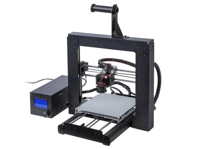
I bought this printer because of reviews and the price. What I didn't expect was how good a print it will make! I've had it now for one year (as of Nov 2016), have done somewhere north of a thousand prints and still find it to be better than most prints I see come off of other, often much more expensive, printers. Given I have seen the price as low as $249 from a US supplier, Monoprice.com, I have to think it is still one of the best values out there today.
Of course, everything can use a little improvement and being a machine design engineer who can't leave anything alone, I set about to find some improvements for this unit. This article explains what I have found and done to my printer and while the already excellent print quality is only slightly better, the consistency from print to print has vastly improved.
Note: There are now several versions of this printer and in some of the newer versions they have improved some of the things I show below. One example is I recently saw a Wanhao Duplicator i3 which had a much stiffer front plate forming so the brace I show below would not really change much. Make sure your printer doesn't already have some of these improvements before spending time and money!
Printer Improvements
Bed Levelling
Thumb Screws
While the bed levelling isn't bad, mine would not stay levelled for more than a few prints. When this happens the first layer gets very ugly to the point of not even laying down.
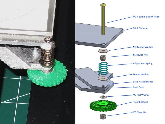
I did a little research and found some printable thumb wheels which made adjusting level easier. I also changed the way the screws mount so that they are solidly bolted to the print platform rather than free floating. This helps keep the platform stable in the X-Y axis. Here are the parts needed to make this upgrade:
- 4x M3 x 30mm Phillips (or Button) head screws
- 4x M3 Flat Washers
- 8x M3 Fender Washers
- 8x M3 Nyloc Nuts
- 4x Printed Thumb Wheels
|
Base Plate Stiffening
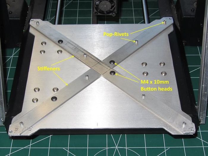
The new thumbscrew set-up helped the levelling be more consistent and a little easier but it still drifted a bit so I took a look at how this might happen and could see that the lower platform which attaches to the Y axis bearings was very flexible and I suspected it was changing shape because of the platform temperature changes. To alleviate this I bought some thin aluminum flatbar, cut some short pieces and riveted them to the lower plate. This made the entire plate much stiffer which did improve the leveling.
- 3ft Aluminum flatbar, 1/8" x 3/4"
- 8x 1/8" Steel Pop Rivets
- 4x M4 x 10mm Button Head Screws
|
Steps
- Remove the base plate and flatten if necessary
- Cut the Aluminum flatbar into three pieces as shown
- Clamp to the base plate, drill and rivet in place
- Using the base plate as a guide, drill the four holes for the bearing block mounts and the four holes for the corner levelling screws
- Shape the corners a little larger than the base plate
- Re-assemble on the printer
My printer now never needs re-leveling except when I change something in the hotend or have to remove it for cleaning.
Thumb Wheel Print File
Print Platform Surface
Use Glass!
To get really good prints you need a print surface that is always flat and will always bond to some degree to the first print layer. At first I simply used Blue painters tape for PLA and ABS and this generally worked. Sometimes I would have to wash the tape with denatured alcohol to remove the wax which was a hassle because then the first layer often stuck too well. This also meant the tape would have to be replaced after the print was done because it got destroyed when I removed the part. I also tried glues and slurry (ABS) and at one point I bought a roll of Kapton tape and tried that but this proved to be much more work than it is worth.
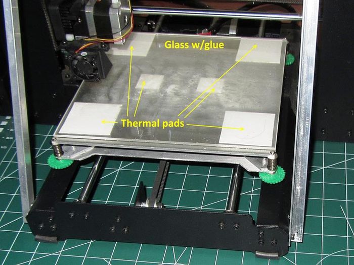
What to do? After doing a little research I found a group who swore the only surface they used was Borosilica glass and Elmers glue stick. After seeing this was actually fairly cheap to try, I bought a piece of Borosilica glass (see "Where to buy" below) and some thermal pad material to hold it in place on the platform. What a difference!!
The thermal pad holds the glass very well so no additional clamps are needed. I simply cut the pad into four 2" squares for the corners and a two 1" sqaures for the center. Then I just cleaned the glass and layed it down. The glass does not move and prints stick very well and once cooled a bit, come up very easily. ABS doesn't warp off the plate either. I can now get many prints before having to completely wash off the glue and re-apply it.
|
Where to Buy
And don't forget the glue stick!

|
Z axis Switch
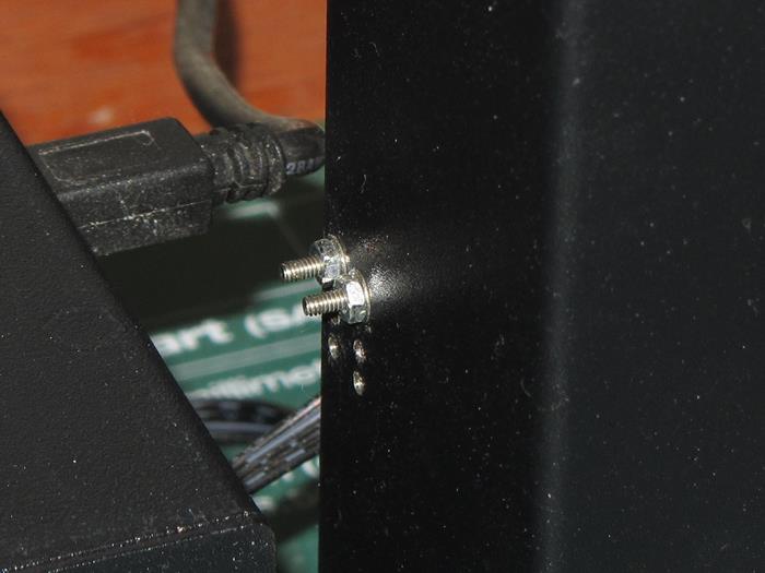
Because you are raising the print platform surface about an 1/8" and the base plate (stiffeners) 1/8" you will need to raise the Z-axis limit switch the same amount, 1/4" (~6mm). This switch is found on the left verticle post of the frame and it already has two sets of holes. Simply drill a new set of holes 1/4" above the highest pair and remount the switch.
If you have a 2mm Tap, then drill and tap these new holes and re-use the original 2mm screws. Alternatively you can drill the holes for clearance (#46 - 0.081") and buy longer 2mm or 2-56 size screws and nuts. Now, re-level the platform and you are done.
|
Frame Stiffening
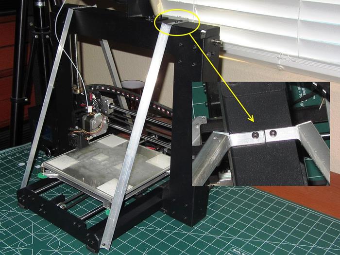
One obvious hardware change I made in the interest of print quality was to stiffen the frame up. This is very simple to do and honestly I don't know why it isn't part of the design. My simple method is to cut some small aluminum angle and form it so it can be bolted to the top and sides of the frame. The parts for this upgrade are:
- 6ft Aluminum angle, 1/16" x 1/2"
- 8x M3 x 10mm Screws
- 8x M3 Nyloc Nuts
|
Steps
- Cut and form the angle pieces as shown in the picture
- Drill the eight holes needed as shown*
- Assemble
- -Alternatively you could drill and tap the steel frame as I did which makes assembly easier.
Now that you have a stiff frame you can add four rubber feet made from some 1/4" tubing slit on one side. Place these on the front and rear of the frame as shown and it will sit more solidly (and print better!)

|
Cooling Fan
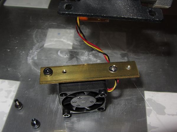
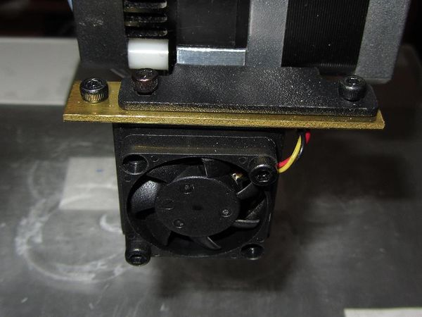
On my Maker Select Printer the front cooling fan was oriented such that the air flow was pointed almost entirely to the right of the nozzle. I have read cooling the print lines after the first layer can be very important to the quality of some materials like PLA so I created a small metal bar to shift it 10mm (~3/8") to the left and 1.5mm (1/16") down. This points it directly towards the center of the print nozzle and a bit closer to the part.
|
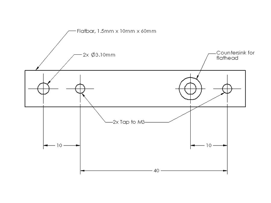
I used a piece of 1/16" x 1/2" Brass flatbar I had laying around. Steel or Aluminum would also work and if you are metric then a 1.5mm x 10mm x 60mm size is perfect. Note: If you make this out of aluminum be careful you don't overtighten the screws in the tapped holes.
|
Here is a simple drawing done in metric to match everything else on the printer.
|
Y-Axis Fix
The Y-axis has two problems with regards to belt alignment and frame flex. In the front, the Y-axis pulley is mounted on a support which is not robust enough to keep from flexing. This causes "layer wandering" to appear in the print on tall prints. Additionally the motor mount in the rear is also not robust enough to keep from flexing.
Motor Fix
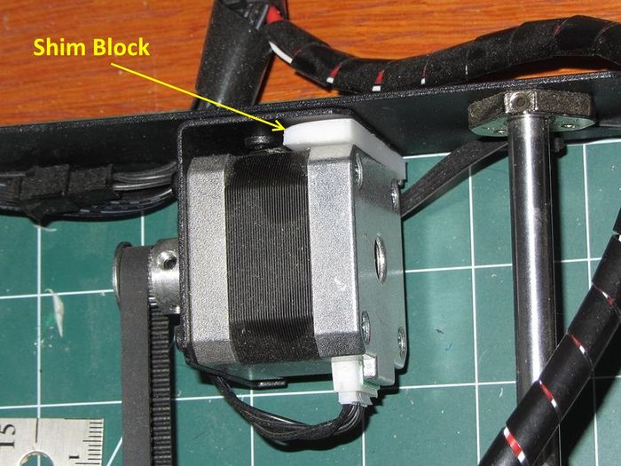
The fix for motor flex is to make a shim block which is 10mm x 5.6mm x 40mm and place it between the rear of the motor and the motor mount frame. This requires a little force to move the motor enough to put the block in.
|
Front Brace
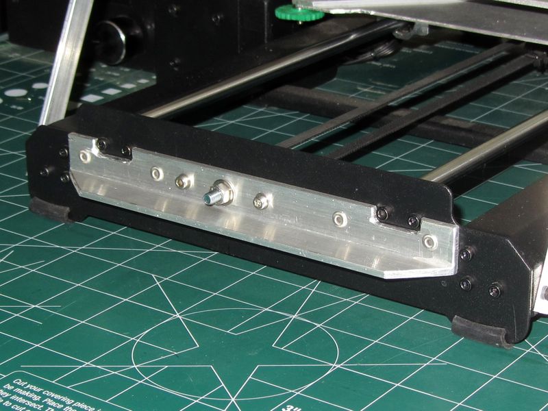
To stop the front frame plate from flexing on my older v1 printer, I used a piece of 1/8" x 3/4" Aluminum angle and cut it to fit around the guide rod screws. I then riveted it to the front plate.
|
Pulley Bracket
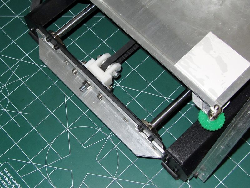
To keep the pulley straight and add an additional means to adjust the belt tension, I found and remixed a couple of parts from Thingiverse. One is a guide block which simply keeps the pulley from rotating out of alignment. The second piece holds the pulley and has an adjustment stud for changing the belt tension. Tension is adjusted by turning the 5mm nut on the front of the stiffener piece.
When drilling the three holes for the pulley block, make sure it is lined up with the attachment under the print platform. In my case the original bracket put the pulley 6mm out of alignment towards the left of the machine.
|
Pulley Bracket/Block Print Files
Re-mixed from: http://www.thingiverse.com/thing:992552
Set-up and Printing
Print Bed Set-up
Prepping the print bed is one of the most important tasks for a successful print. There are many ways to do this and the google hits are endless if you search. I have had good success with using blue painters tape wiped down with rubbing alcohol for both PLA and ABS but it does have its drawbacks. One is you will very often have to replace the tape and every time you do this you need to re-level the print bed.
As shown above, I now use a piece of Borosilicate glass and a light coating of Elmers Glue Stick glue. This works very well, hardly ever requires re-leveling and lasts quite a long time. It is very easy to remove the glue by picking the glass up and soaking it in warm water. A new coating then goes down in seconds and you are printing again.
Leveling
For this I use an automotive "feeler gage" with a thickness of 0.003" (0.08mm). You can also use a cut strip from a sheet of normal weight printer paper. I run the printhead down to the "Home" position then move the printhead to each corner and check with the feeler gage. It should just have a slight amount of resistance and not visibly move the print-head up when pushed under the nozzle. I check each corner at least three times and I do this when both the nozzle and print platform are fully heated (important!).
Repetier Software Set-up
The first task is to get the printer to connect and this is done in the Print Settings screens. The following images show the settings I am currently using. Note:In Windows you may have to go into Device Manager to see which COM port to use after you plug in the printer.
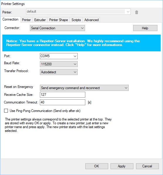
|
On this screen set the Extruder and Bed temperature to values equal to or higher than what is set up in Cura. Also make sure you have a "Park" position defined which is different than "Home" in that this is where the nozzle goes at the end of the print.
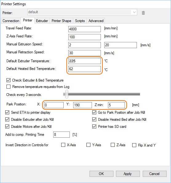
|
All Maker Select printers come with a 0.4mm nozzle but in my case the documentation said it was 0.5mm. Set it to 0.4mm in the screen below.
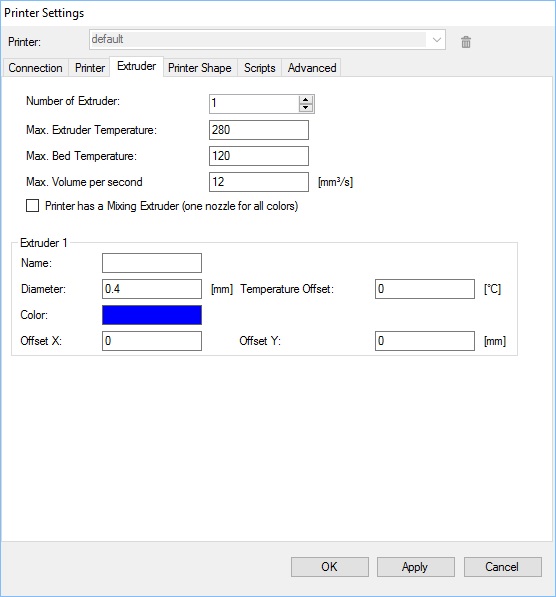
|
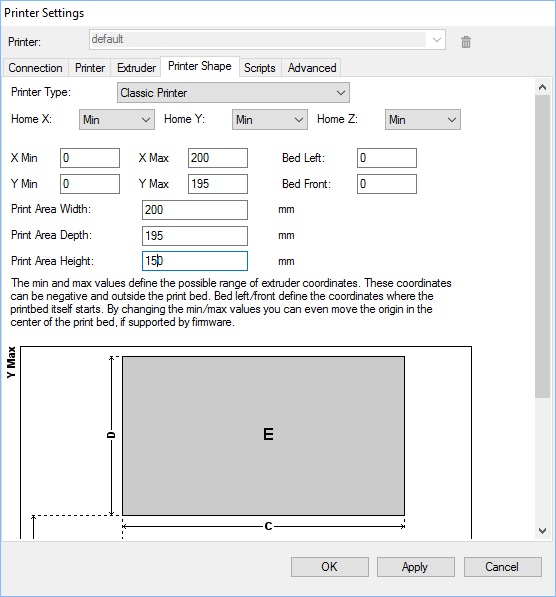
|
Cura Configuration
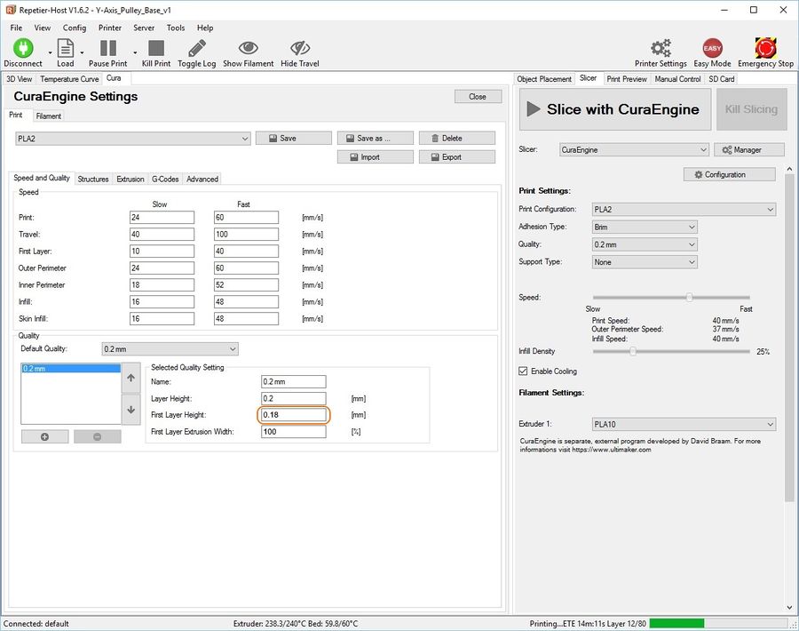
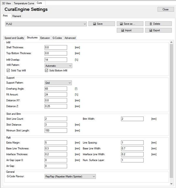
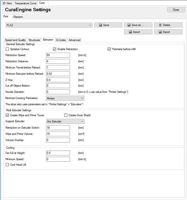
The following screens show how I have the Cura slicer currently set-up for PLA. Your settings will likely differ depending on the filament you use, environmental factors and the complexity of your prints.
Update: On this first screen I have circled the "First Layer Height". Previously this was set to 0.3mm which while it works OK, I have found that setting this to a value equal to 90% of the layer height works much better. I have also changed the "First Layer Extrusion Width" to the default of 100%.
|
|
|
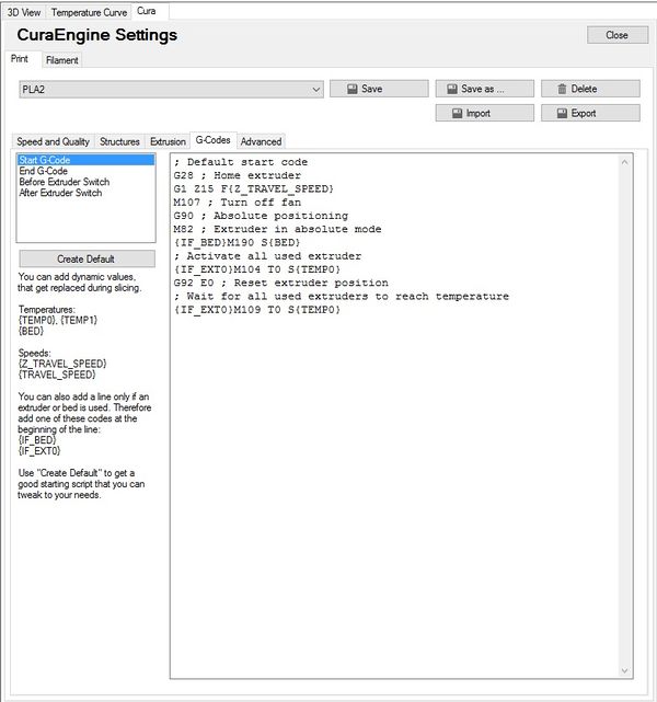
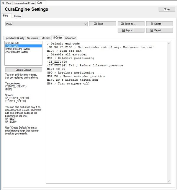
In this screen you will want to put some custom G-code so your printer behaves well at print start-up. Search Google for a G-code reference or click the link below if you want to know more. I've copied it here so you can copy and paste into your set-up screen.
- ; Default start code
- G28 ; Home extruder
- G1 Z15 F{Z_TRAVEL_SPEED}
- M107 ; Turn off fan
- G90 ; Absolute positioning
- M82 ; Extruder in absolute mode
- {IF_BED}M190 S{BED}
- ; Activate all used extruder
- {IF_EXT0}M104 T0 S{TEMP0}
- G92 E0 ; Reset extruder position
- ; Wait for all used extruders to reach temperature
- {IF_EXT0}M109 T0 S{TEMP0}
|
And again! Here is the end G-code you can copy and paste:
- ; Default end code
- ;G1 X0 Y0 Z130 ; Get extruder out of way. Uncomment to use!
- M107 ; Turn off fan
- ; Disable all extruder
- G91 ; Relative positioning
- {IF_EXT0}T0
- {IF_EXT0}G1 E-1 ; Reduce filament pressure
- M104 T0 S0
- G90 ; Absolute positioning
- G92 E0 ; Reset extruder position
- M140 S0 ; Disable heated bed
- M84 ; Turn steppers off
|
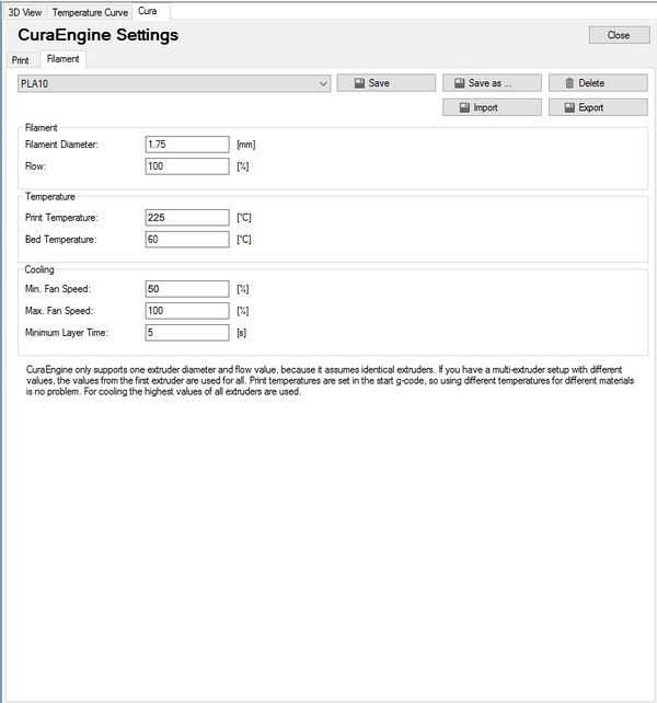
In this screen you will want to put the Print Temperature recommended by the filament manufacturer. If you don't know then start with 220 for PLA and 240 for ABS. A Bed Temperature of 60 works well for me with PLA but if you are printing ABS, this should be 90 - 105.
|
Temperature Settings
Extruder Temperature
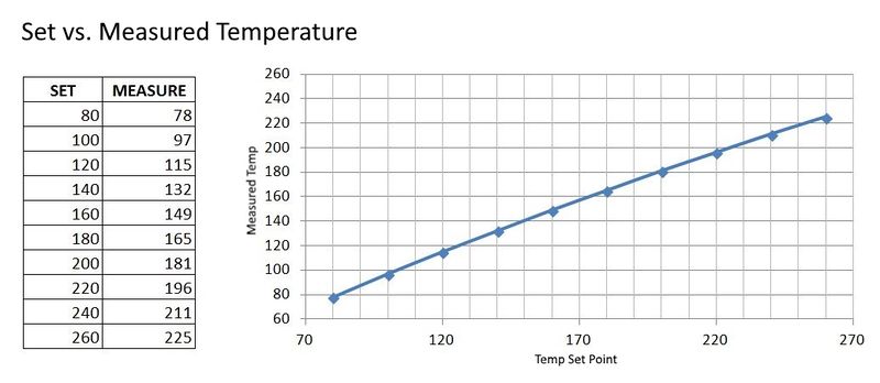
All three printers I have owned have had variations in the extruder temperature and this can greatly affect print quality (not to mention frustration level!). Below I have put together a chart showing what I found on my Maker Select with regards to temperature setting and actual measured temperature. To do this I used both an IR temp gun and a separate temperature probe which is calibrated and connected through a data unit to my computer.
|
Because of the variation I have seen I would suggest you try and find a way to accurately measure your extruder nozzle temperature. IR temp guns can be found on Ebay relatively cheap. Make sure you get one capable of measuring up to 300C.
Bed Temperature
Interestingly enough, all three printers I have owned have had no issue with bed temperature. They have all been within a degree or two with respect to set vs. measured temperature.
Print Load and Print
And finally it is time to print!
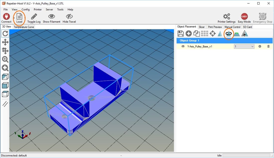
Start by Loading a print file by clicking the "Load" button and searching for your parts STL file. Once loaded it will be displayed virtually on the print bed oriented as it was in the modeling software that created it. In Solidworks, the Front plane is the print base. Use the Position tool (circled) to re-orient the part to the desired orientation.
|
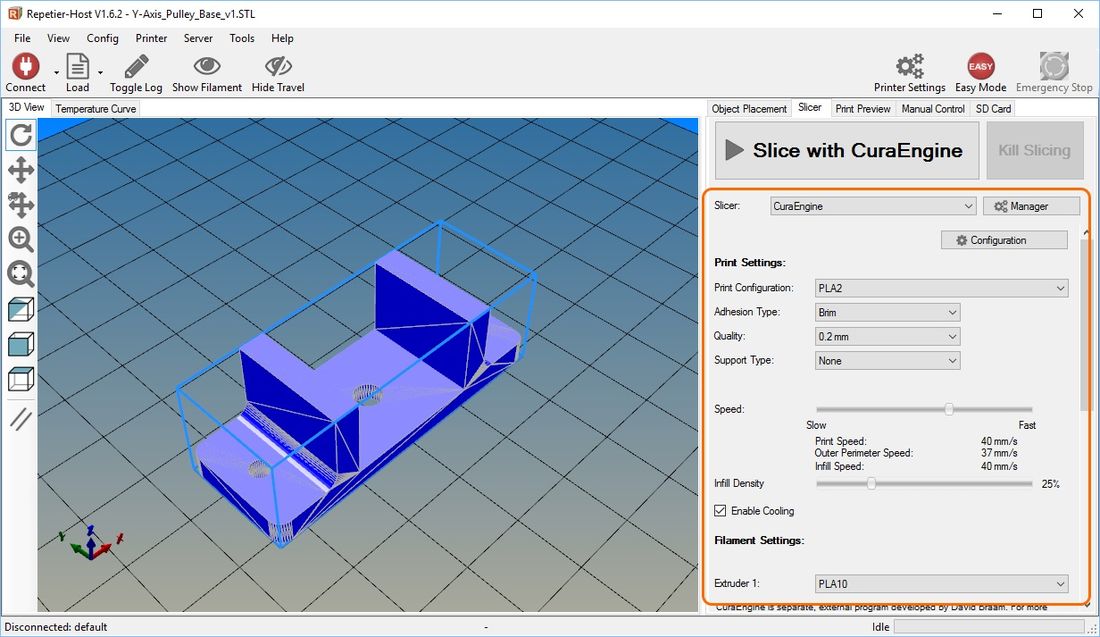
Next, click on the "Slicer" tab and set the initial parameters for Adhesion, Speed and Infill. If this is your first print, make the Adhesion "Brim" and keep it slow, around 28-30mm/s, with infill around 30%. Don't worry about Quality at this time, keep it at 0.2mm.
|
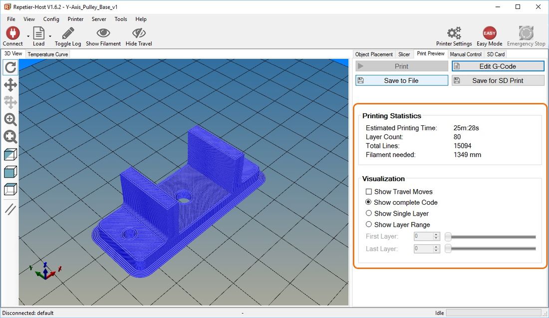
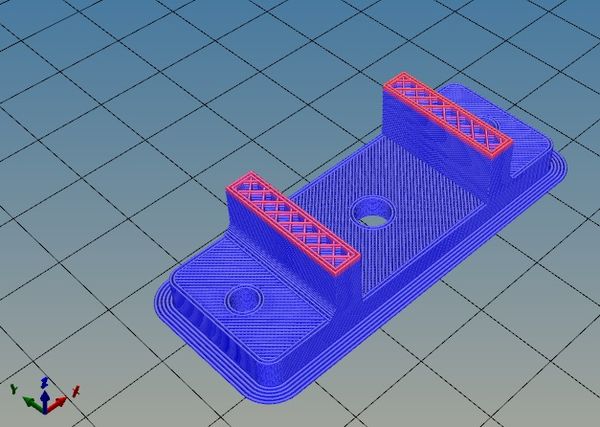
Click on "Slice with CuraEngine" and when slicing completes you will see it show up with all its lines and layers. You will now see the estimated time to print, the amount of filament it will need and the layer count. You can use the Visualization tools to look at any layer.
|
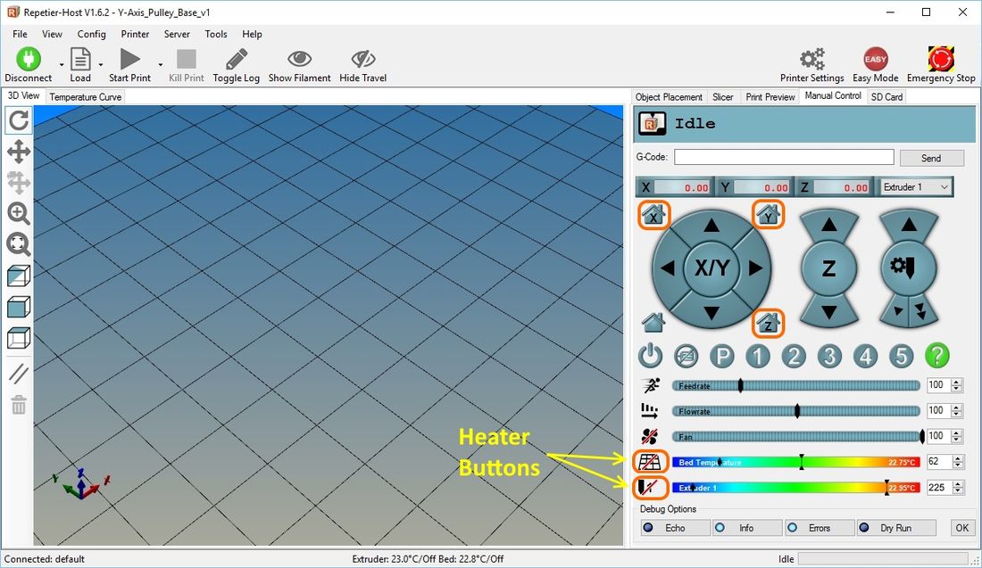
Next, if you haven't already done so, click on "Connect". Also if the "Easy Mode" button is green, click it as well (it should be red).

|
Now click on each "Home" button for X, Y and Z (circled). Click the Bed and Nozzle heater buttons and make sure you see the temperature start to rise. If the print head "Homes" correctly and the heaters are both working , click the "Start Print" button. The print will start as soon as both heaters have reached their temps.
|
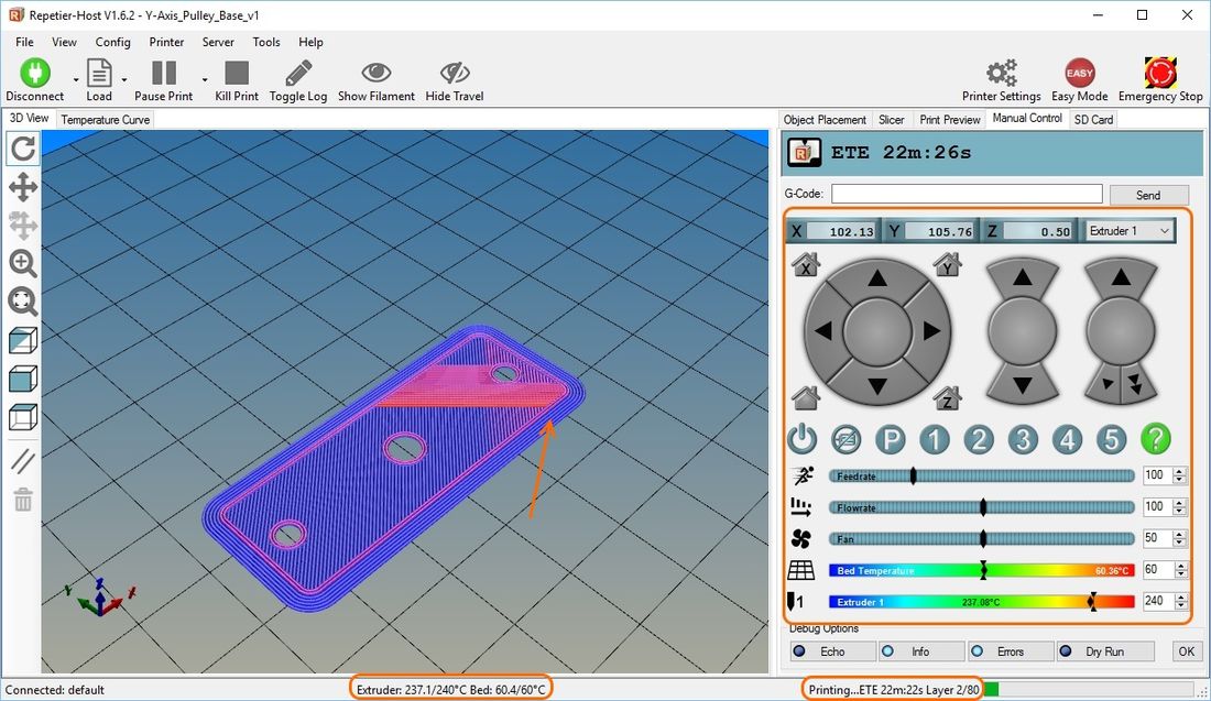
You're Printing!
You now see an animation of what the print is doing and at the bottom of the screen you can see the temps, the estimated time left to completion and the current print layer. The different colored lines represent temperature.
|
|
|
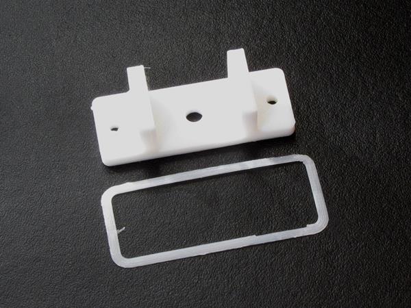
| Finished part with Brim removed |
More Mods!
Of course the mods never stop!
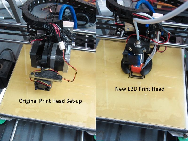
One issue I kept finding was a small amount of chatter on the Y axis. After much tuning and set up changes I decided to convert to a Bowden feed system which takes the motor and pinch roller assembly off the X-axis carriage. This makes the carriage significantly lighter and less prone to chatter. It also usually increases the speed capability.
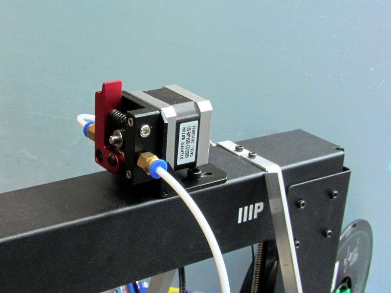
For a print head (see parts list below) I chose an inexpensive E3D style that came with everything needed including a silicone hot end glove and plenty of PTFE tubing. For the pinch roller I found an all metal unit that came with a bracket which mounts the whole affair to the top filament reel mount holes.
To mount the new print head I found a nice piece on Thingiverse which I slightly modded to fit my exact unit. I also printed a new style fan mount that bolts to the back of the lower cearing block.
Before and After of the print head-
|
New pinch roller set-up-
|
Parts
- E3D Print Head - Gulfcoast Robotics All Metal V6 Bowden Extruder
- New Pinch Roller set - Right Hand Remote Bowden Drive
- Print Parts - e3D Bowden Mount by CarstenD
- New Cooling Fan mount - CiiiCooler for Wanhao i3/Maker Select by Pawpawpaw85
- New Cooling Fan mount - CiiiCooler for Wanhao i3/Maker Select by Pawpawpaw85
See Also
Comments? Questions?