Difference between revisions of "390 Degree Geared Pan and Tilt"
(→Where to buy the parts) |
(→See Also) |
||
| Line 245: | Line 245: | ||
:: In the US - <u>[https://www.servocity.com/32-pitch-plain-bore-gears-with-hub-acetyl ServoCity]</u> | :: In the US - <u>[https://www.servocity.com/32-pitch-plain-bore-gears-with-hub-acetyl ServoCity]</u> | ||
:: In Europe - <u>[https://www.steplab.net StepLab]</u> | :: In Europe - <u>[https://www.steplab.net StepLab]</u> | ||
| − | |||
| − | |||
| − | |||
| − | |||
| − | |||
<br><br><br> | <br><br><br> | ||
[[Category:Contents]] | [[Category:Contents]] | ||
[[Category:Gimbals]] | [[Category:Gimbals]] | ||
Latest revision as of 14:01, 6 January 2023
Contents |
|
| It's all about Gears! |
Introduction
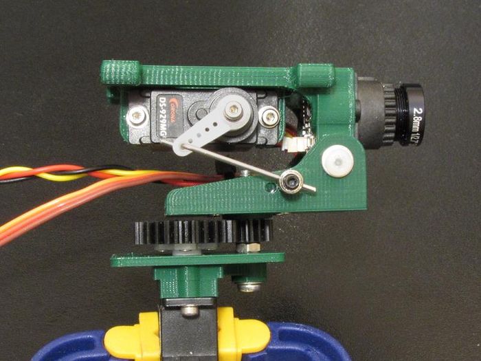
This project is really an extension of my Forward Offset Pan & Tilt and my recent Lightweight Pan and Tilt. The Lightweight P&T used printed gears and this unit uses "Store Bought" Acetyl gears which (for me) work much more smoothly. Built to the below specs, it will turn 390 degrees and tilt 110 degrees total. It is designed around the Turnigy™ TGY-R5180MG 180 Degree Metal Gear Analog Servo and a pair of 32 pitch Acetyl gears from ServoCity. It is a bit more robust and with the new gears much smoother. It will cover the entire 390 degree sweep with standard servo output of 1000µs to 2000µs and centers very well.
Configurations
I built this P&T for two different configurations and four arrangements. The two configurations are with a simple camera deck without tilt and one with tilt. The four arrangements are:
- 1. Simple HD camera deck at 4 degrees tilt
- Total weight - 29.3g
- 2. HD camera Tilt deck
- Total weight - 51.6g
- 3. HD camera Tilt deck for small 18mm box type FPV camera
- Total weight - ~63g
- 4. HD camera Tilt deck for 21mm box type FPV camera
- Total weight - ~65g

|
| Three of the four arrangements |
Parts
The parts needed for everything shown are the following:
Hardware
- M3 x 30mm full thread machine screw
- 2x M3 x 6mm nylon screws
- 4x M3 flatwashers
- 2x M3 hex nuts
- 1x M3 nyloc nut
- 8x M2 x 8mm socket head cap screws
- 8x M2 flat washers
- 4x M2 x 6mm flathead screws
- 4x #0 x 3/16" Flathead sheet metal screws
- 1x 3mm ID x 0.1875" OD x 10mm long aluminum bushing
- 1x Turnigy RS5180MG (good) servo or Turnigy™ TGY-180D servo (better)
- 1x 9-12g Micro servo (Corona DS929MG shown)
- 1x ServoCity 12T, 32 Pitch plain bore acetyl gear - part #SPBD32-33-12
- 1x ServoCity 26T, 32 Pitch plain bore acetyl gear - part #SPBD32-34-26
Print Parts
- GPNT_Camera_Mount_18mm_v3
- GPNT_Camera_Mount_21mm_v1
- GPNT_Camera_Mount_Base_v2
- GPNT_Camera_Plate_4Deg_v01
- GPNT_Pinion_Gear_Mount_v4
- GPNT_Servo_Plate_v24
Servo Deck
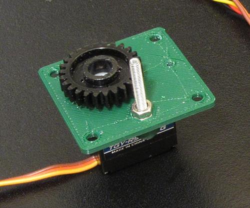
The servo plate is a key part in that the dimension between the pinion gear axle and the servo center is critical to the operation. This part needs to be printed on a high quality setting at 0.2mm resolution or better.
|
| Complete servo plate assembly |
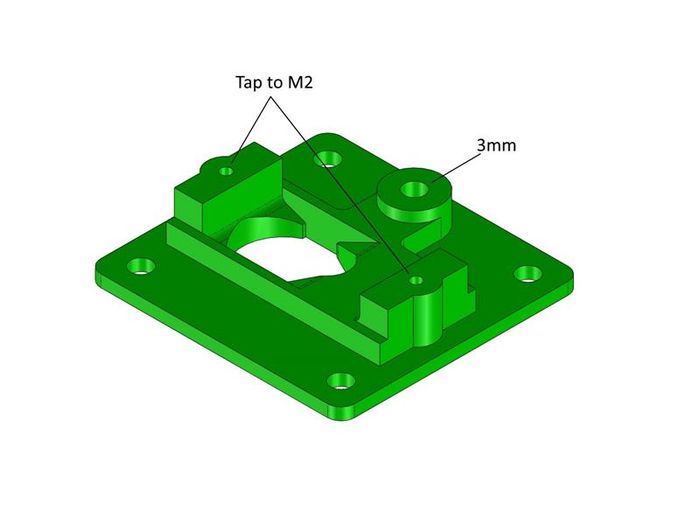
Once printed, use a 2mm tap to cut threads in the holes for the servo ears. It is best to tap these holes from the top side. Clean up the 3mm hole for the pinion axle and make sure the hex cavity will fit an M3 hex nut.
|
Add the Pinion Axle and Servo
The pinion axle is made from the full-thread M3 x 30mm machine screw. Now push the screw through the axle hole, spin the two hex nuts on and tighten them so the first one is fully seated in the hex cavity and the second one is tight against the first.
Add the servo using two of the M2 x 8mm screws and M2 flat washers.
Drive Gear Prep and Mount
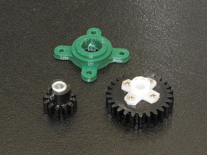
The drive gear is a 26 tooth gear that needs the gear boss cut off and a servo wheel or cross mount fit to it using flathead sheet metal screws. To cut the boss off I simply clamped it in a small vise and used a balsa saw to cut it flush with the gear face.
NOTE - TRICKY PART! This can be a difficult operation as the servo wheel or cross must be centered near perfectly on the gear. The method I used was to wrap the center hub of the servo cross with a thin strip of cellophane tape so it fit snugly into the gear center hole. I then hand-drilled four holes through the cross into the gear, flipped it over and screwed it to the gear using the #0 x 3/16" flat head sheet metal screws.
Pinion Gear Mount
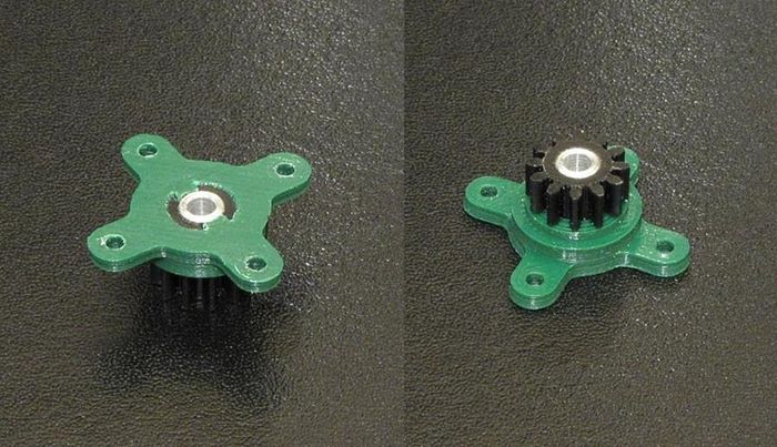
The pinion gear mount can be a little tricky to print as it needs to be a tight push fit. If it is too loose, you can make up the slack with a strip of tape around the gear boss. If it is too tight, you may be able to sand the gear boss enough to fit or you will have to modify the inside dimension and re-print.
You will need to cross drill the gear boss with a 2.5mm drill bit centered 3mm below the edge of the boss then trim out two notches from this to fit the bosses inside the gear mount print. When pushed in, the gear should be against the gear mount and the two notches engaged.
The last part of this is to make and insert the aluminum bushing. This part is made from a piece of #83030 K&S 3/16" x 0.035" wall aluminum tubing which can be found at hobby stores and hardware stores like ACE Hardware (or online).
Now cut the aluminum tube to a length of 10mm, de-burr any sharp edges and press it into the pinion gear assembly. You may need to very carefully drill out the ID of the aluminum tubing with a #32 drill bit (0.116" or 2.95mm) if it is too tight on the M3 screw post. This is best done using a drill press and a new, sharp drill bit.
|
| Gear pieces |
|
| Finished pinion mount assembly |
Pan Deck
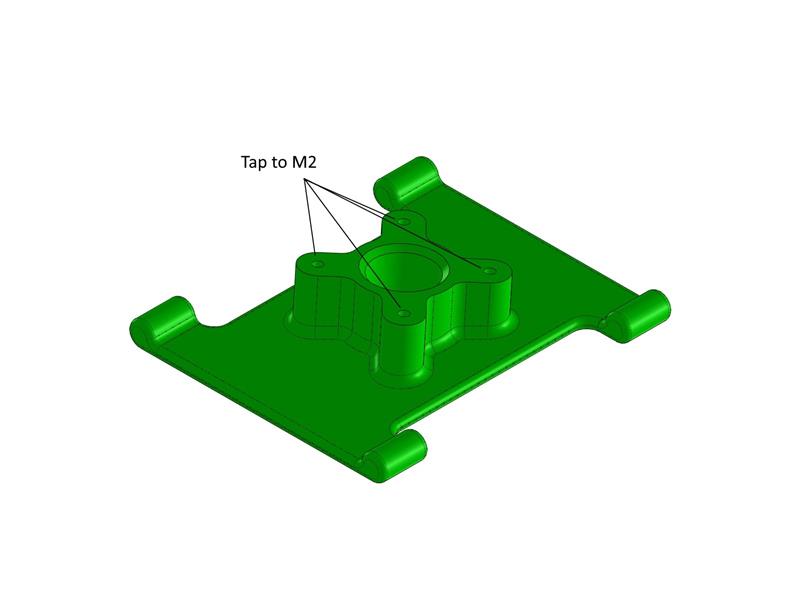
The Pan Deck is used when no tilt is desired. It is designed to accomodate a Mobius, Mobius Mini and Runcam types of action cameras. Using the 2mm tap, tap the four gear mount holes from the top side.
|
| Pan deck |
Pan & Tilt Deck
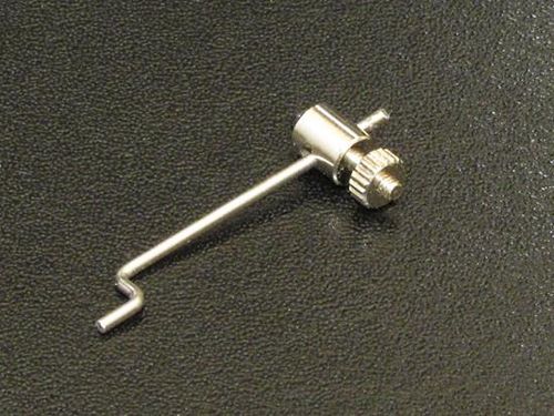
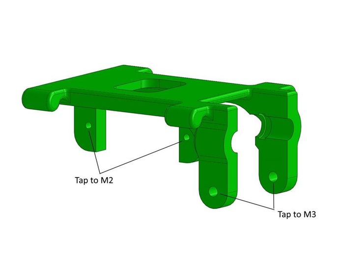
The Pan & Tilt deck assembly is a variation from some of my earlier work. There are two versions for two different size FPV cameras. To fit this assembly to this new P&T design I just changed the mount base to accommodate the pinion gear mount assembly instead of a servo horn. It uses a typical 9-12g servo for tilt and piece of link wire with a swivel wire connector. You will need to tap the two servo mounts with an M2 tap and the pivot ears with an M3 tap. It pivots on the two nylon M3 screws which can be secured by putting a tiny drop of CA on the back of the screw threads.
|
| Tilt linkage parts |
|
| P&T Deck |
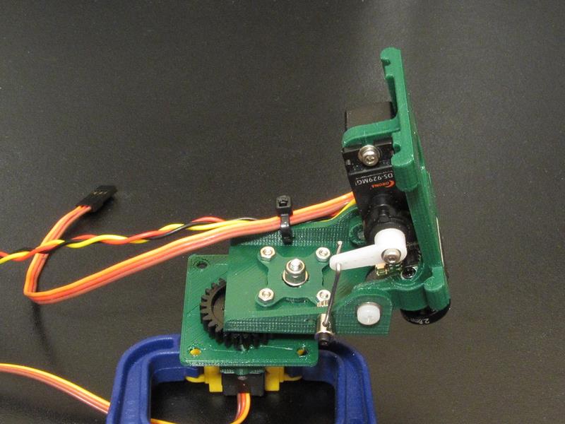
|
| Pan & Tilt deck assembly |
Optional Camera Deck
This optional camera deck is to accommodate the RunCam Split as both the HD camera and the FPV camera. It has four threaded M3 holes for stand-offs to mount the circuit board and a protection plate and a bracket with six 2.1mm holes to mount the camera body.
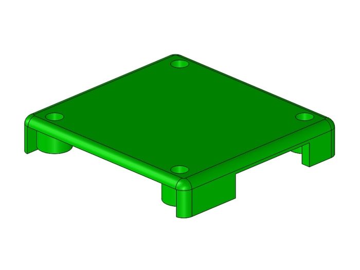
|
| RC Split Mount Cover |
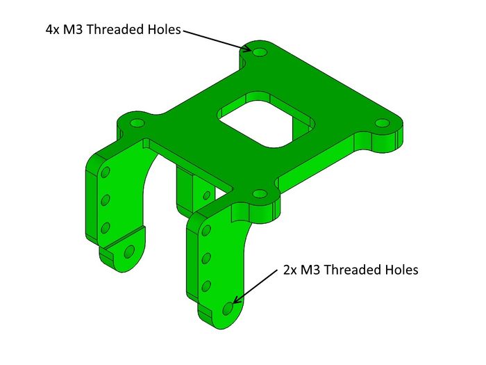
|
| RC Split Mount showing the 6 tapped M3 holes |
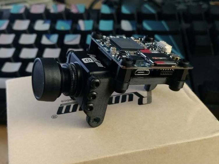
|
| Printed by FB poster |
Optional Deck STL Files
Note: This file set contains two camera decks and two top covers.
- 52062_v1r2 is to fit the older base plates and is 28mm wide at the pivot ears
- 52062_v2r1 is to fit the newer base plates found in the Pan & Tilt Parts Catalog
- 52067_v1r4 & 52076_v1r2 together make the top cover for the RCSplit V1 camera
- 52135_v1r1 is the top cover for the RCSplit V2 camera
Credit!
Many thanks to posters Daryn Owens and Erwin Quilloy for their ideas in this design!
Final Assembly
Follow these assembly steps to complete this build-
- 1. Take the finished servo plate with servo and axle mounted and add the drive gear assembly. Do not install the servo screw yet.
- 2. Take the Pan or Pan and Tilt assembly with the gear mount attached, slide it onto the axle and engage the gears.
- 3. Rotate the gears and make sure they are tight but not binding.
- 4. Power the servo using a receiver and your TX with no trims, adjustments or extended travel set-up. Rotate the servo back and forth and make sure it operates smoothly.
- 5. on your transmitter center the servo then pull the P&T assembly off to rotate it to where you want center to be. If you can't get it perfect, rotate the pinion gear mount 90 degrees and try again. You can also rotate the drive gear one tooth at a time to get a finer adjustment.
- 6. Once centering is complete, screw the drive gear down and add the M3 locknut and M3 flat washer to the pinion gear mount axle. Tighten until it just touches the pinion gear mount but doesn't bind it.
- 7. Test and go fly!
See Also
Project 3D Print Files
The following are the 3D print ZIP files used in this specific build. For more versions and information, please see my Thingiverse postings here:
Mark_q Thingiverse Designs
Where to buy the parts