Difference between revisions of "Aircraft Power Systems - The ESC"
(→See Also) |
(→Why this matters) |
||
| (15 intermediate revisions by the same user not shown) | |||
| Line 9: | Line 9: | ||
== Introduction == | == Introduction == | ||
| − | This article serves to outline, in an over-simplified way, the most basic workings of a brushless ESC. This is not a deep dive in electronics, circuitry or theory but rather a super simplified view of what an ESC does. My hope is this knowledge will help folks gain a little more understanding about these fairly sophisticated electronic systems and make better decisions about component matching when building and flying their aircraft.<br><br> | + | This article serves to outline, in an ideal, over-simplified way, the most basic workings of a brushless ESC. This is not a deep dive in electronics, circuitry or theory but rather a super simplified view of what an ESC does. My hope is this knowledge will help folks gain a little more understanding about these fairly sophisticated electronic systems and make better decisions about component matching when building and flying their aircraft.<br><br> |
| + | |||
| + | An excellent reference, written in 1994 by Robert J. Boucher (A.K.A AstroBob) is the "AstroFlight Electric Motor Handbook". While the AstroFlight Handbook is very dated with respect to available components and technology in 2018, it is a wonderful source of knowledge and understanding. For the purpose of this article the section on "High Rate Control" on page 45 will go into more detail than I provide here.<br><br> | ||
=== ESC Operation === | === ESC Operation === | ||
| Line 17: | Line 19: | ||
First and foremost, the way an ESC regulates motor speed and power '''<u>is not done</u>''' by changing the <u>peak</u> voltage to the motor. Most folks think this way because the motors have a published "kv" value which is given in terms of RPM/volt. The way an ESC actually works is a little more technical but still an easy concept.<br><br> | First and foremost, the way an ESC regulates motor speed and power '''<u>is not done</u>''' by changing the <u>peak</u> voltage to the motor. Most folks think this way because the motors have a published "kv" value which is given in terms of RPM/volt. The way an ESC actually works is a little more technical but still an easy concept.<br><br> | ||
| − | Rather than changing the voltage to the motor to vary speed and power, the ESC provides control using a Pulse Width Modulation (PWM) signal. A PWM signal has the voltage turning ON and OFF at a high frequency and rather than varying the voltage linearly, it varies the percentage of time the peak voltage is turned ON and OFF. A graph showing a PWM signal with a 50% ON-time (or 50% Duty Cycle) looks like this: | + | Rather than changing the voltage to the motor to vary speed and power, the ESC provides control using a Pulse Width Modulation (PWM) signal. A PWM signal has the voltage turning ON and OFF at a high frequency, usually 8,000 to 15,000 times per second, and rather than varying the voltage linearly, it varies the percentage of time the peak voltage is turned ON and OFF. A graph showing a PWM signal with a 50% ON-time (or 50% Duty Cycle) looks like this: |
<br> | <br> | ||
{| border="0" cellspacing="1" cellpadding="1" align="center" | {| border="0" cellspacing="1" cellpadding="1" align="center" | ||
|- | |- | ||
| − | | align="center" | [[File:PS11.jpg| | + | | align="center" | [[File:PS11.jpg|600px]] |
|} | |} | ||
<br> | <br> | ||
| Line 37: | Line 39: | ||
{| border="0" cellspacing="1" cellpadding="1" align="center" | {| border="0" cellspacing="1" cellpadding="1" align="center" | ||
|- | |- | ||
| − | | align="center" | [[File:PS13.jpg| | + | | align="center" | [[File:PS13.jpg|600px]] |
|} | |} | ||
<br> | <br> | ||
| − | What you see now is when the FET's are switched ON, the current rises up to try and meet the load demand of the motor. When the FET's are switched OFF, magnetic energy stored in the motor windings has to be absorbed by the ESC. This "waste current" is a little bit like "Water Hammer" in a plumbing system. In conventional ESC's, during the OFF cycle, this waste current is dealt with using diodes and much of it is converted to heat.<br><br> | + | What you see now is when the FET's are switched ON, the current rises up to try and meet the load demand of the motor. When the FET's are switched OFF, magnetic energy stored in the motor windings has to be absorbed by the ESC. This "waste current" is a little bit like "Water Hammer" in a plumbing system and just like in the plumbing system, this can cause damage if not dissipated in some way. In conventional ESC's, during the OFF cycle, this waste current is dealt with using diodes and much of it is converted to heat.<br><br> |
==== Why this matters ==== | ==== Why this matters ==== | ||
| − | Since you now see power delivery <u>is always 100%</u> at varying times, you should understand the logic behind why it is very important to keep maximum current demanded by the motor/prop combo below what the ESC is rated for! In other words - It makes no difference if you never run 100% throttle as 100% is always demanded | + | Since you now see power delivery <u>is always 100%</u> at varying times, you should understand the logic behind why it is very important to keep maximum current demanded by the motor/prop combo below what the ESC is rated for! In other words - '''It makes no difference''' if you never run 100% throttle as '''100% is always demanded''' from the ESC!<br><br> |
So, the bottom line is: | So, the bottom line is: | ||
<br> | <br> | ||
---- | ---- | ||
| − | ''' | + | '''<span style="font-size:120%"><u>You must size or re-size the ESC</u> to the maximum current the motor/prop combo demands at full throttle, not the motors published maximum current.</span>''' |
---- | ---- | ||
| − | + | <br> | |
==== ESC Sizing for Fixed Wing FPV ==== | ==== ESC Sizing for Fixed Wing FPV ==== | ||
| Line 72: | Line 74: | ||
:* [[X-UAV Mini Talon Motor Selection]] | :* [[X-UAV Mini Talon Motor Selection]] | ||
:* [https://www.rcgroups.com/forums/showthread.php?952523-too-long-battery-wires-will-kill-ESC-over-time-precautions-solutions-workarounds ESC Long Battery Wires] | :* [https://www.rcgroups.com/forums/showthread.php?952523-too-long-battery-wires-will-kill-ESC-over-time-precautions-solutions-workarounds ESC Long Battery Wires] | ||
| + | <br> | ||
| − | < | + | === References === |
| + | |||
| + | : <u>[http://astrobobb.com/electric_motor_handbook.pdf AstroFlight Electric Motor Handbook]</u> | ||
| + | : ©1994, Robert J. Boucher (A.K.A AstroBob) | ||
| + | <br> | ||
=== Comments? Questions? === | === Comments? Questions? === | ||
| Line 82: | Line 89: | ||
<br><br><br> | <br><br><br> | ||
| − | [[Category: | + | [[Category:Contents]] |
Latest revision as of 12:55, 14 August 2018
© Mark Qvale - 4 August, 2018

|
Introduction
This article serves to outline, in an ideal, over-simplified way, the most basic workings of a brushless ESC. This is not a deep dive in electronics, circuitry or theory but rather a super simplified view of what an ESC does. My hope is this knowledge will help folks gain a little more understanding about these fairly sophisticated electronic systems and make better decisions about component matching when building and flying their aircraft.
An excellent reference, written in 1994 by Robert J. Boucher (A.K.A AstroBob) is the "AstroFlight Electric Motor Handbook". While the AstroFlight Handbook is very dated with respect to available components and technology in 2018, it is a wonderful source of knowledge and understanding. For the purpose of this article the section on "High Rate Control" on page 45 will go into more detail than I provide here.
ESC Operation
It is critical you understand basicaly how a brushless ESC operates so you don't create electrical problems that can damage or destroy your plane.
First and foremost, the way an ESC regulates motor speed and power is not done by changing the peak voltage to the motor. Most folks think this way because the motors have a published "kv" value which is given in terms of RPM/volt. The way an ESC actually works is a little more technical but still an easy concept.
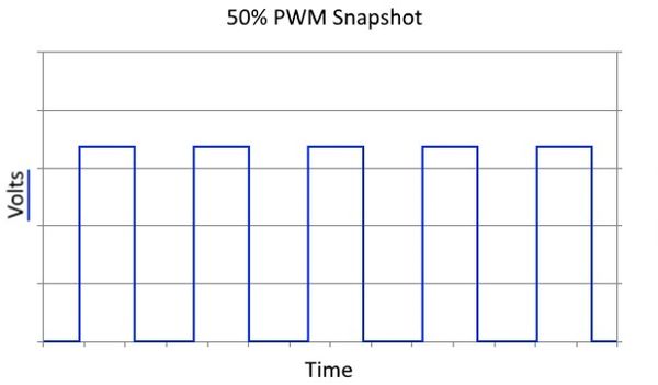
Rather than changing the voltage to the motor to vary speed and power, the ESC provides control using a Pulse Width Modulation (PWM) signal. A PWM signal has the voltage turning ON and OFF at a high frequency, usually 8,000 to 15,000 times per second, and rather than varying the voltage linearly, it varies the percentage of time the peak voltage is turned ON and OFF. A graph showing a PWM signal with a 50% ON-time (or 50% Duty Cycle) looks like this:

|
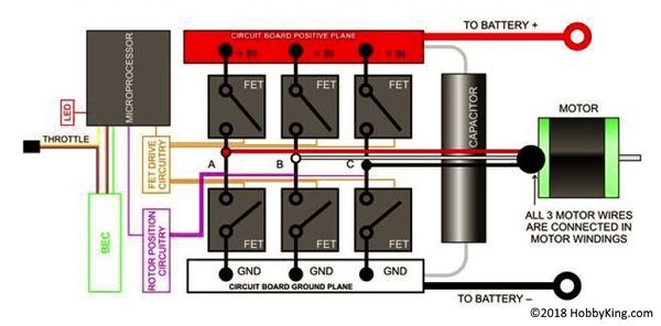
So, how does this work? On board the ESC is a micro-controller that manages a set of IC's, also known as Field Effect Transistors or FET's, which are basically simple high-power on/off electronic switches. To vary the output to the motor this micro-controller tells the FET's how long to stay ON at a given throttle value. In an ideal ESC then, 0% throttle results in the FET's being turned on 0% of the time, 50% throttle results in an on-time of 50% and 100% throttle provides on-time at 100%.
You can see by the image above, the peak voltage never changes, only the length of time it is ON. This is important to understand because it is the current demanded by the motor, based on load, during this on-time that will make or break your ESC.
This means 100% of the power is being made available to the motor any time the FET's are switched on.
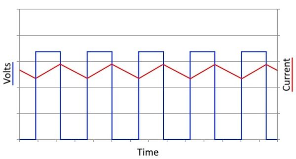
If we overlay what the current is doing when the voltage is switched ON and OFF, you can see how the current behaves:

|
What you see now is when the FET's are switched ON, the current rises up to try and meet the load demand of the motor. When the FET's are switched OFF, magnetic energy stored in the motor windings has to be absorbed by the ESC. This "waste current" is a little bit like "Water Hammer" in a plumbing system and just like in the plumbing system, this can cause damage if not dissipated in some way. In conventional ESC's, during the OFF cycle, this waste current is dealt with using diodes and much of it is converted to heat.
Why this matters
Since you now see power delivery is always 100% at varying times, you should understand the logic behind why it is very important to keep maximum current demanded by the motor/prop combo below what the ESC is rated for! In other words - It makes no difference if you never run 100% throttle as 100% is always demanded from the ESC!
So, the bottom line is:
You must size or re-size the ESC to the maximum current the motor/prop combo demands at full throttle, not the motors published maximum current.
ESC Sizing for Fixed Wing FPV
If you fly FPV using conventional balsa or foam constructed airplanes like the XUAV Mini Talon or Zeta FX61, etc. there are two more bits of information you need to consider.
- Since these planes fly at relatively slow speeds for long periods of time (up to an hour or more) the amount of air cooling the internal components receive is vastly reduced.
- At low throttle values, conventional ESC's create more waste current and heat then they do at higher throttle values.
There are two ways to mitigate these two FPV conditions-
- 1. Size the ESC well above the maximum current demanded by the motor/prop combo you have chosen. The larger, more robust components will be better to deal with the waste current and heat. Personally I would add at least 20A to the size typically used.
-or-
- 2. Purchase an ESC with the components, circuitry and software that will provide an "Active Freewheeling" function which is designed to be more efficient and run much cooler at lower throttle levels. Two examples of these are the Hobbywing V5 series which also have a very robust and clean 8A SBEC and the FlyColor Raptor 390 Opto BLHeli series ESC's.
See Also
References
- AstroFlight Electric Motor Handbook
- ©1994, Robert J. Boucher (A.K.A AstroBob)
Comments? Questions?