Difference between revisions of "DIY - Benchtop CNC"
(→Downloads) |
(→New Laser Module) |
||
| (89 intermediate revisions by the same user not shown) | |||
| Line 1: | Line 1: | ||
<br> | <br> | ||
| − | <i><small> | + | [[File:cc_image.png|20px]]<i><small> Mark Qvale - March, 2020</small></i><br> |
{| cellspacing="1" cellpadding="1" width="95%" border="0" | {| cellspacing="1" cellpadding="1" width="95%" border="0" | ||
|- | |- | ||
| − | | align="left" valign="top" width=" | + | | align="left" valign="top" width="35%" | __TOC__ |
| − | | align="right" width=" | + | | align="right" valign="top" width="65%" | [[File:CNC001.JPG|600px]] |
|- | |- | ||
| | | | ||
| − | | align="right" width="50%" | | + | | align="right" width="50%" | |
|} | |} | ||
| − | + | <br> | |
| − | + | ||
| − | + | ||
== <br>Introduction == | == <br>Introduction == | ||
| Line 26: | Line 24: | ||
<br> | <br> | ||
| − | After all this (and much, much more) I decided how to proceed with my own version of a bench-top CNC for foam cutting and other jobs. This article then, is my version using | + | After all this (and much, much more) I decided how to proceed with my own version of a bench-top CNC for foam cutting and other jobs. This article then, is my version using an old 3D printer and ideas found in online articles and other resources. |
<br> | <br> | ||
| − | All designs found in this article are licensed under '''<u>[https://creativecommons.org/licenses/by-nc-sa/4.0/ Creative Commons Attribution-NonCommercial-ShareAlike 4.0 International]</u>''' | + | '''NOTE: This machine is not and was never intended to be a metal cutting CNC mill. It is intended to be a lightweight engraver/ plotter/ foam cutter/ template cutter.''' |
| + | <br> | ||
| + | |||
| + | All designs found in this article are licensed under [[File:cc_image.png|24px]] - '''<u>[https://creativecommons.org/licenses/by-nc-sa/4.0/ Creative Commons Attribution-NonCommercial-ShareAlike 4.0 International]</u>''' | ||
<br><br> | <br><br> | ||
| Line 39: | Line 40: | ||
|} | |} | ||
<br> | <br> | ||
| − | + | Some Numbers:<br> | |
: Base Size - 24" x 48" x 13.5" (61cm x 122cm x 35cm) | : Base Size - 24" x 48" x 13.5" (61cm x 122cm x 35cm) | ||
::Base Width w/respect to Y axis = Y tube Length + 1/4" (6mm) | ::Base Width w/respect to Y axis = Y tube Length + 1/4" (6mm) | ||
| Line 98: | Line 99: | ||
<br><br> | <br><br> | ||
| − | {| border="1" cellspacing="1" cellpadding="1" align=" | + | {| border="1" cellspacing="1" cellpadding="1" align="center" |
|- | |- | ||
| width="200" align="Left" | '''Image''' | | width="200" align="Left" | '''Image''' | ||
| Line 203: | Line 204: | ||
| align="Left" | Gantry Drive Mount | | align="Left" | Gantry Drive Mount | ||
| align="Left" | [http://www.itsqv.com/QVM/files/CNC/80014.STL 80014.STL] | | align="Left" | [http://www.itsqv.com/QVM/files/CNC/80014.STL 80014.STL] | ||
| − | |||
| − | |||
| − | |||
| − | |||
| − | |||
| − | |||
| − | |||
| − | |||
| − | |||
| − | |||
| − | |||
| − | |||
| − | |||
| − | |||
| − | |||
| − | |||
| − | |||
| − | |||
| − | |||
| − | |||
| − | |||
| − | |||
| − | |||
| − | |||
| − | |||
| − | |||
| − | |||
| − | |||
| − | |||
| − | |||
| − | |||
| − | |||
| − | |||
| − | |||
| − | |||
| − | |||
| − | |||
| − | |||
| − | |||
| − | |||
| − | |||
| − | |||
| align="Left" | Print in ABS or PLA at 0.2mm resolution and 50% infill | | align="Left" | Print in ABS or PLA at 0.2mm resolution and 50% infill | ||
|} | |} | ||
| Line 252: | Line 211: | ||
<br><br> | <br><br> | ||
:80016, Needle Cutter Needle Holder is printed at 0.1mm resolution and 80% infill. | :80016, Needle Cutter Needle Holder is printed at 0.1mm resolution and 80% infill. | ||
| − | + | <br> | |
| − | === | + | === Printing Details and Times === |
The chart below outlines print details with estimated print time and filament usage for the parts in this project. | The chart below outlines print details with estimated print time and filament usage for the parts in this project. | ||
| Line 265: | Line 224: | ||
{| border="0" cellspacing="1" cellpadding="1" align="center" | {| border="0" cellspacing="1" cellpadding="1" align="center" | ||
|- | |- | ||
| − | | align="center" | [[File: | + | | align="center" | [[File:CNC032c.jpg|895px]] |
|} | |} | ||
<br> | <br> | ||
| − | : Total print time | + | The following is a summary of the machines parts only, no tool attachment parts: |
| − | : Total number of parts - | + | : Total print time - 52hrs, 50min |
| + | : Total number of parts - 23 | ||
: Total filament used - ~0.76kg | : Total filament used - ~0.76kg | ||
<br><br> | <br><br> | ||
| Line 408: | Line 368: | ||
<br><br> | <br><br> | ||
| − | === | + | === Making Accurate Metal Parts === |
<br> | <br> | ||
It is important on a project like this to get the dimensional accuracy of all parts as close as possible to avoid assembly and operational differences (problems). Below are details of how I do this on three of the critical parts without the benefit of using a vertical milling machine. | It is important on a project like this to get the dimensional accuracy of all parts as close as possible to avoid assembly and operational differences (problems). Below are details of how I do this on three of the critical parts without the benefit of using a vertical milling machine. | ||
| Line 446: | Line 406: | ||
{| border="0" cellspacing="1" cellpadding="1" width="500" align="center" | {| border="0" cellspacing="1" cellpadding="1" width="500" align="center" | ||
|- | |- | ||
| − | | align="center" | [[File: | + | | align="center" | [[File:CNC056.JPG|700px]] |
|- | |- | ||
| − | | align="center" | | + | | align="center" | Finishing the corner brackets |
|} | |} | ||
<br> | <br> | ||
| Line 458: | Line 418: | ||
== Fasteners == | == Fasteners == | ||
<br> | <br> | ||
| − | The chart below lists all the fasteners used on my first build. Part numbers are from my own part database and prices shown are from <u>[https://www.boltdepot.com/Default.aspx BoltDepot.com]</u> as of April 2, 2020. | + | The chart below lists all the fasteners used on my first build. Part numbers and descriptions are from my own part database and prices shown are from <u>[https://www.boltdepot.com/Default.aspx BoltDepot.com]</u> as of April 2, 2020. |
<br> | <br> | ||
| Line 471: | Line 431: | ||
This section takes a look at some of the major sub assemblies and how they are intended to be built. All designed parts were done in SolidWorks and are licensed as '''<u>[https://creativecommons.org/licenses/by-nc-sa/4.0/ "Share Alike, Non-Commercial"]</u>'''. | This section takes a look at some of the major sub assemblies and how they are intended to be built. All designed parts were done in SolidWorks and are licensed as '''<u>[https://creativecommons.org/licenses/by-nc-sa/4.0/ "Share Alike, Non-Commercial"]</u>'''. | ||
<br><br> | <br><br> | ||
| − | + | ||
| + | One of the great ideas from the folks at V1 Engineering was to use metal conduit for the Y-axis and X-axis slides. The total cost for these pieces is around $18 and they were purchased from a local big box hardware store. The tube is called EMT Conduit or "Electric Metallic Tube (EMT) Conduit". If you go this route, make sure to check the pieces you buy for straightness and a consistent finish. After cutting to length I did sand the tubes with 220 and 400 grit sandpaper to get a nice smooth motion from the two gantries. | ||
| + | <br><br> | ||
| + | |||
| + | As an example, here is a link to one of the tubes (#60005 EMT Conduit Tubing, 1/2"): | ||
| + | : Link: '''<u>[https://www.homedepot.com/p/1-2-in-x-10-ft-Electric-Metallic-Tube-EMT-Conduit-853428/100400405 EMT Conduit]</u>''' | ||
| + | <br><br> | ||
| + | |||
| + | The below link will get you a complete parts list. All part numbers shown are my own and have no relation to any existing manufacturers part. They are simply an easy way to reference each component. | ||
<br><br> | <br><br> | ||
: Link: '''<u>[http://www.itsqv.com/QVM/files/CNC/CNC_Parts_v1.1.pdf CNC_Parts_v1.1.pdf]</u>''' | : Link: '''<u>[http://www.itsqv.com/QVM/files/CNC/CNC_Parts_v1.1.pdf CNC_Parts_v1.1.pdf]</u>''' | ||
| Line 520: | Line 488: | ||
| align="center" | [[File:CNC047.JPG|800px]] | | align="center" | [[File:CNC047.JPG|800px]] | ||
|} | |} | ||
| + | <br> | ||
| + | |||
| + | === Base and Vacuum Table === | ||
| + | <br> | ||
| + | This is my "As-Built" base which includes structure for adding a shop vacuum to help secure the work piece. For the top I used a piece of HD Particle board and for the structure I used typical 1 x 3 White-wood found at the local big box store (Lowes). All structure pieces were ripped on a table saw to ~2.4" and the hole for my shop-vac was cut to 1-3/4" with a hole saw. | ||
| + | <br> | ||
| + | {| border="0" cellspacing="1" cellpadding="1" width="900" align="center" | ||
| + | |- | ||
| + | | align="center" | [[File:CNC053.JPG|800px]] | ||
| + | |} | ||
| + | <br> | ||
| + | To drill the deck holes, I laid out the hole pattern on a piece of 1/4" hard-board, secured it in place on the deck piece against the X and Y axis (marked) and drilled through both. This gave me a template to use for making (purple) foam work support pieces which are needed when using the Needle Cutter. I simply place the template on top of a new piece of foam, lining up the two X and Y edges, and quickly hot-wire through each hole. | ||
| + | <br> | ||
| + | {| border="0" cellspacing="1" cellpadding="1" width="900" align="center" | ||
| + | |- | ||
| + | | align="center" | [[File:CNC055.jpg|500px]] | ||
| + | |- | ||
| + | | align="center" | Template and 3/4" purple foam piece | ||
| + | |} | ||
| + | <br><br> | ||
| + | |||
| + | == Tool Attachments == | ||
| + | <br> | ||
| + | {| border="0" cellspacing="1" cellpadding="1" width="900" align="center" | ||
| + | |- | ||
| + | | align="center" | [[File:CNC058.JPG|900px]] | ||
| + | |} | ||
| + | <br> | ||
| + | Tool attachments are what make this project! Here I show four different tools which all work very well and are all attached via four M4 socket head screws. | ||
<br> | <br> | ||
| Line 553: | Line 550: | ||
<br><br> | <br><br> | ||
| − | === | + | === Drag-Knife Tool === |
<br> | <br> | ||
| − | + | I wanted a way to cut decals and paint templates so I took a look at professional Drag Knives to get an idea and this is what I came up with. It is built with the same bearings I used in the CNC sliders, a spring for pre-load, an Xacto Knife and a couple of printed parts. | |
<br> | <br> | ||
{| border="0" cellspacing="1" cellpadding="1" width="900" align="center" | {| border="0" cellspacing="1" cellpadding="1" width="900" align="center" | ||
|- | |- | ||
| − | | align="center" | [[File: | + | | align="center" | [[File:CNC046.JPG|850px]] |
|} | |} | ||
<br> | <br> | ||
| − | + | ||
| + | === Dremmel Router Tool === | ||
| + | <br> | ||
| + | Always wanted a way to do some engraving and I already had the Dremmel. This is just a simple clamp and because of the type of coupler I have on the lead screw, the cutter will move a small amount vertically. Even with the movement, it still does a very nice job on soft wood. | ||
| + | <br> | ||
| + | '''NOTE: There are many models of the Dremmel Tools! This clamp fits the "Dremmel MultiPro model 395"''' | ||
<br> | <br> | ||
{| border="0" cellspacing="1" cellpadding="1" width="900" align="center" | {| border="0" cellspacing="1" cellpadding="1" width="900" align="center" | ||
|- | |- | ||
| − | | align="center" | [[File: | + | | align="center" | [[File:CNC039.JPG|850px]] |
| + | |} | ||
| + | <br> | ||
| + | |||
| + | === Laser Engraving/Cutting Tool === | ||
| + | <br> | ||
| + | Always wanted a way to do some Laser engraving and cutting! I found an inexpensive, 5 watt Laser Module (On Sale - $89) and thought I would give it a try. I did a couple iterations of the mount and added an air-assist nozzle which made a huge difference in burn and cut quality | ||
| + | <br> | ||
| + | '''NOTE: These parts are designed specifically for the <u>[https://www.banggood.com/450nm-5W-Laser-Engraving-Module-Blue-Light-With-TTL-Modulation-p-1337358.html?rmmds=search&cur_warehouse=CN Banggood 5w Laser Module]</u> and likely will not fit other modules''' | ||
| + | <br> | ||
| + | {| border="0" cellspacing="1" cellpadding="1" width="900" align="center" | ||
|- | |- | ||
| − | | align="center" | | + | | align="center" | [[File:CNC091.JPG|850px]] |
|} | |} | ||
| − | <br><br> | + | <br> |
| + | |||
| + | === Tool Print Parts === | ||
| + | <br> | ||
| + | The following are print parts for the Needle Cutter Tool and the Plotter/Pen Holder Tool: | ||
| + | <br> | ||
| + | |||
| + | {| border="1" cellspacing="1" cellpadding="1" align="center" | ||
| + | |- | ||
| + | | width="200" align="Left" | '''Image''' | ||
| + | | width="65" align="Center" | '''Part Number''' | ||
| + | | width="50" align="Center" | '''QTY''' | ||
| + | | width="200" align="Left" | '''Part Description''' | ||
| + | | width="80" align="Center" | '''Print File''' | ||
| + | | align="Left" | '''Part Notes''' | ||
| + | |- | ||
| + | | align="Left" | [[File:80015sm.JPG]] | ||
| + | | align="Center" | '''80015''' | ||
| + | | align="Center" | 1 | ||
| + | | align="Left" | Needle Cutter Mount | ||
| + | | align="Left" | [http://www.itsqv.com/QVM/files/CNC/80015.STL 80015.STL] | ||
| + | | align="Left" | Print in ABS or PLA at 0.2mm resolution and 50% infill | ||
| + | |- | ||
| + | | align="Left" | [[File:80016sm.JPG]] | ||
| + | | align="Center" | '''80016''' | ||
| + | | align="Center" | 1 | ||
| + | | align="Left" | Needle Cutter, Needle Holder | ||
| + | | align="Left" | [http://www.itsqv.com/QVM/files/CNC/80016.STL 80016.STL] | ||
| + | | align="Left" | '''Print in ABS or PLA at 0.1mm resolution and 80% infill''' | ||
| + | |- | ||
| + | | align="Left" | [[File:80017sm.JPG]] | ||
| + | | align="Center" | '''80017''' | ||
| + | | align="Center" | 1 | ||
| + | | align="Left" | Pen Holder Mount | ||
| + | | align="Left" | [http://www.itsqv.com/QVM/files/CNC/80017.STL 80017.STL] | ||
| + | | align="Left" | Print in ABS or PLA at 0.2mm resolution and 50% infill | ||
| + | |- | ||
| + | | align="Left" | [[File:80018sm.JPG]] | ||
| + | | align="Center" | '''80018''' | ||
| + | | align="Center" | 2 | ||
| + | | align="Left" | Pen Holder Spring Bracket | ||
| + | | align="Left" | [http://www.itsqv.com/QVM/files/CNC/80018.STL 80018.STL] | ||
| + | | align="Left" | Print in ABS or PLA at 0.2mm resolution and 50% infill | ||
| + | |- | ||
| + | | align="Left" | [[File:80019sm.JPG]] | ||
| + | | align="Center" | '''80019''' | ||
| + | | align="Center" | 1 | ||
| + | | align="Left" | Drag Knife Lower Mount | ||
| + | | align="Left" | [http://www.itsqv.com/QVM/files/CNC/80019.STL 80019.STL] | ||
| + | | align="Left" | Print in ABS or PLA at 0.2mm resolution and 50% infill | ||
| + | |- | ||
| + | | align="Left" | [[File:80020sm.JPG]] | ||
| + | | align="Center" | '''80020''' | ||
| + | | align="Center" | 1 | ||
| + | | align="Left" | Drag Knife Upper Mount | ||
| + | | align="Left" | [http://www.itsqv.com/QVM/files/CNC/80020.STL 80020.STL] | ||
| + | | align="Left" | Print in ABS or PLA at 0.2mm resolution and 50% infill | ||
| + | |- | ||
| + | | align="Left" | [[File:80021sm.JPG]] | ||
| + | | align="Center" | '''80021''' | ||
| + | | align="Center" | 1 | ||
| + | | align="Left" | Dremmel Clamp Lower Mount | ||
| + | | align="Left" | [http://www.itsqv.com/QVM/files/CNC/80021.STL 80021.STL] | ||
| + | | align="Left" | Print in ABS or PLA at 0.2mm resolution and 50% infill | ||
| + | |- | ||
| + | | align="Left" | [[File:80022sm.JPG]] | ||
| + | | align="Center" | '''80022''' | ||
| + | | align="Center" | 1 | ||
| + | | align="Left" | Dremmel Clamp Upper Mount | ||
| + | | align="Left" | [http://www.itsqv.com/QVM/files/CNC/80022.STL 80022.STL] | ||
| + | | align="Left" | Print in ABS or PLA at 0.2mm resolution and 50% infill | ||
| + | |- | ||
| + | | align="Left" | [[File:80025sm.JPG]] | ||
| + | | align="Center" | '''80025''' | ||
| + | | align="Center" | 1 | ||
| + | | align="Left" | Laser Module Mount | ||
| + | | align="Left" | [http://www.itsqv.com/QVM/files/CNC/80025.STL 80025.STL] | ||
| + | | align="Left" | Print in ABS or PLA at 0.2mm resolution and 50% infill | ||
| + | |- | ||
| + | | align="Left" | [[File:80026sm.JPG]] | ||
| + | | align="Center" | '''80026''' | ||
| + | | align="Center" | 1 | ||
| + | | align="Left" | Air-Assist Nozzle Mount | ||
| + | | align="Left" | [http://www.itsqv.com/QVM/files/CNC/80026.STL 80026.STL] | ||
| + | | align="Left" | Print in ABS or PLA at 0.2mm resolution and 50% infill | ||
| + | |- | ||
| + | | align="Left" | [[File:80027sm.JPG]] | ||
| + | | align="Center" | '''80027''' | ||
| + | | align="Center" | 1 | ||
| + | | align="Left" | Laser Focus Knob | ||
| + | | align="Left" | [http://www.itsqv.com/QVM/files/CNC/80027.STL 80027.STL] | ||
| + | | align="Left" | Print in ABS or PLA at 0.2mm resolution and 50% infill | ||
| + | |} | ||
| + | {{Clear1}} | ||
== Controls == | == Controls == | ||
| − | This is a brief description of what I use to control the CNC. There are | + | This is a brief description of what I use to control the CNC. There are three control boards shown here, initial as-built 3D control board and two purpose built CNC control set-ups. I wanted to keep the cost low and the control system simple. To that end, all the systems here need a computer (laptop) to work. For a control user interface I am using the free Universal Gcode Sender (UGS) software linked below-<br> |
| + | : '''<u>[https://winder.github.io/ugs_website/ Universal Gcode Sender]</u>''' | ||
<br> | <br> | ||
| Line 597: | Line 703: | ||
<br><br> | <br><br> | ||
| − | === | + | === Original 3018 CNC Board === |
<br> | <br> | ||
{| border="0" cellspacing="1" cellpadding="1" width="900" align="center" | {| border="0" cellspacing="1" cellpadding="1" width="900" align="center" | ||
| Line 607: | Line 713: | ||
<br> | <br> | ||
| − | + | This board, which is labeled "Developower v2.0" did not work well for me. It was OK as long as I didn't attempt to activate the limit switches, something I feel is mandatory. I did download and install the most current stable firmware and I also swapped out the clone Arduino Nano with an original equipment one but neither the current firmware or the new Arduino board made any difference. I also tried changing out the Makerbot limit switches I was using with industrial Micro-Switch units and again, no change. At one point, when trying to activate the limit switches, it dumped all the machine eeprom settings and stopped working completely. | |
| + | <br> | ||
| + | |||
| + | From here I did a little more research and came up with another inexpensive option (see below). In any case I would not recommend going with the 3018 CNC board. | ||
| + | <br><br> | ||
| + | |||
| + | === SainSmart 3-Axis Control Board === | ||
| + | |||
| + | <br> | ||
| + | {| border="0" cellspacing="1" cellpadding="1" width="900" align="center" | ||
| + | |- | ||
| + | | align="center" | [[File:CNC071.jpg|550px]] | ||
| + | |- | ||
| + | | align="center" | SainSmart Board | ||
| + | |} | ||
| + | <br> | ||
| + | |||
| + | I found this board on Amazon but you can also get it direct from Sainsmart here: '''<u>[https://www.sainsmart.com/collections/genmitsu-cnc/products/3-axis-grbl-usb-driver-controller-board Sainsmart]</u>'''. I am really impressed! It worked right out of the box including limit switches and active homing. It was very easy to set-up and I now have a case printed up to help protect it. It has an on-board power relay to manage a spindle motor and a TTL capable Laser output/input. | ||
| + | <br> | ||
| + | {| border="0" cellspacing="1" cellpadding="1" width="900" align="center" | ||
| + | |- | ||
| + | | align="center" | [[File:CNC073.JPG|850px]] | ||
| + | |} | ||
| + | <br> | ||
| + | |||
| + | With a price of around $25, it is a great bargain. | ||
<br><br> | <br><br> | ||
| Line 614: | Line 745: | ||
A few project pictures: | A few project pictures: | ||
<br> | <br> | ||
| − | {| border="0" cellspacing="1" cellpadding="1" width=" | + | {| border="0" cellspacing="1" cellpadding="1" width="900" align="center" |
|- | |- | ||
| align="center" | [[File:CNC012.JPG|760px]] | | align="center" | [[File:CNC012.JPG|760px]] | ||
| Line 621: | Line 752: | ||
|} | |} | ||
<br> | <br> | ||
| − | {| border="0" cellspacing="1" cellpadding="1" width=" | + | {| border="0" cellspacing="1" cellpadding="1" width="900" align="center" |
|- | |- | ||
| align="center" | [[File:CNC020.JPG|760px]] | | align="center" | [[File:CNC020.JPG|760px]] | ||
| Line 628: | Line 759: | ||
|} | |} | ||
<br> | <br> | ||
| − | {| border="0" cellspacing="1" cellpadding="1" width=" | + | {| border="0" cellspacing="1" cellpadding="1" width="900" align="center" |
|- | |- | ||
| align="center" | [[File:CNC021.JPG|760px]] | | align="center" | [[File:CNC021.JPG|760px]] | ||
| Line 635: | Line 766: | ||
|} | |} | ||
<br> | <br> | ||
| − | {| border="0" cellspacing="1" cellpadding="1" width=" | + | {| border="0" cellspacing="1" cellpadding="1" width="900" align="center" |
|- | |- | ||
| align="center" | [[File:CNC052.JPG|600px]] | | align="center" | [[File:CNC052.JPG|600px]] | ||
| Line 642: | Line 773: | ||
|} | |} | ||
<br> | <br> | ||
| − | {| border="0" cellspacing="1" cellpadding="1" width=" | + | {| border="0" cellspacing="1" cellpadding="1" width="900" align="center" |
|- | |- | ||
| align="center" | [[File:CNC054.JPG|600px]] | | align="center" | [[File:CNC054.JPG|600px]] | ||
|- | |- | ||
| align="center" | Dremmel Clamp | | align="center" | Dremmel Clamp | ||
| + | |} | ||
| + | <br> | ||
| + | {| border="0" cellspacing="1" cellpadding="1" width="900" align="center" | ||
| + | |- | ||
| + | | align="center" | [[File:CNC093.JPG|600px]] | ||
| + | |- | ||
| + | | align="center" | 5w Laser Mount | ||
|} | |} | ||
<br><br> | <br><br> | ||
| Line 655: | Line 793: | ||
<br> | <br> | ||
<br> | <br> | ||
| − | {| border="0" cellspacing="1" cellpadding="1" width=" | + | {| border="0" cellspacing="1" cellpadding="1" width="900" align="center" |
|- | |- | ||
| align="center" | [[File:CNC034.jpg|800px]] | | align="center" | [[File:CNC034.jpg|800px]] | ||
| Line 662: | Line 800: | ||
|} | |} | ||
<br> | <br> | ||
| − | Next is the result of the first part set I cut out of 5mm Foam-Board. The fuselage parts are low density and the wing is high density. Cuts needed a very small amount of sanding to clean off paper remnants and to smooth out some very minor bumps. | + | Next is the result of the first part set I cut out of 5mm Foam-Board (total cost - $4!). The fuselage parts are low density and the wing is high density. Cuts needed a very small amount of sanding to clean off paper remnants and to smooth out some very minor bumps. |
<br> | <br> | ||
| − | {| border="0" cellspacing="1" cellpadding="1" width=" | + | {| border="0" cellspacing="1" cellpadding="1" width="900" align="center" |
|- | |- | ||
| align="center" | [[File:CNC033.JPG|800px]] | | align="center" | [[File:CNC033.JPG|800px]] | ||
| Line 673: | Line 811: | ||
Here are the first parts all glued together and ready to go fly. Wingspan is 32" and total material cost is ~$4!! | Here are the first parts all glued together and ready to go fly. Wingspan is 32" and total material cost is ~$4!! | ||
<br> | <br> | ||
| − | {| border="0" cellspacing="1" cellpadding="1" width=" | + | {| border="0" cellspacing="1" cellpadding="1" width="900" align="center" |
|- | |- | ||
| align="center" | [[File:CNC038.JPG|900px]] | | align="center" | [[File:CNC038.JPG|900px]] | ||
|- | |- | ||
| align="center" | First completed plane and a fantastic flyer! | | align="center" | First completed plane and a fantastic flyer! | ||
| + | |} | ||
| + | <br> | ||
| + | And now the Juka cut out in 1.9Lb EPP foam! | ||
| + | <br> | ||
| + | {| border="0" cellspacing="1" cellpadding="1" width="900" align="center" | ||
| + | |- | ||
| + | | align="center" | [[File:CNC078.JPG|900px]] | ||
| + | |} | ||
| + | <br> | ||
| + | First laser cut part, a wing rib as a test piece which came out beautiful! Cut out of 1/16" balsa at 500mm/min and 4 passes. | ||
| + | <br> | ||
| + | {| border="0" cellspacing="1" cellpadding="1" width="900" align="center" | ||
| + | |- | ||
| + | | align="center" | [[File:CNC094.jpg|800px]] | ||
| + | |} | ||
| + | <br> | ||
| + | {| border="0" cellspacing="1" cellpadding="1" width="900" align="center" | ||
| + | |- | ||
| + | | align="center" | [[File:CNC092.jpg|900px]] | ||
|} | |} | ||
<br><br> | <br><br> | ||
| Line 690: | Line 847: | ||
</td></tr></table> | </td></tr></table> | ||
</plainhtml> | </plainhtml> | ||
| + | <br><br> | ||
| + | |||
| + | == Updates!! == | ||
| + | <br> | ||
| + | === The Old Board === | ||
| + | <br> | ||
| + | The Sainsmart board worked well until I started getting more serious with the laser. When I started cutting materials using multiple passes, I began to see slippage (lost steps) on the Y axis. First thing I did was replace the very old, very used steppers with new Stepperonline, 0.9deg motors. Well it ran smoother to more slippage. Next I tried changing out the A4898 drivers with TMC2208 drivers. This didn't work well as these TMC2208 drivers are not compatible with this particular Sainsmart board. At this point I came to the conclusion this board could use an upgrade.<br><br> | ||
| + | |||
| + | === New Board === | ||
| + | <br> | ||
| + | This new board is made or distributed by a company called "Annoytools". It is a 4 axis board with two drives for the two Y axis motors (nothing shared). It is a 32bit card with a USB-C interface and needs 24v to run. Since I already bought the TMC2208 drivers I put these in and reset the vref. | ||
| + | <br> | ||
| + | It is super quiet now and very smooth running but there is still an issue with the Y-axis accuracy. | ||
| + | <br><br> | ||
| + | {| border="0" cellspacing="1" cellpadding="1" width="900" align="center" | ||
| + | |- | ||
| + | | align="center" | [[File:New_Board.jpg|600px]] | ||
| + | |- | ||
| + | | align="center" | New Board! | ||
| + | |} | ||
| + | <br><br> | ||
| + | {| border="0" cellspacing="1" cellpadding="1" width="900" align="center" | ||
| + | |- | ||
| + | | align="center" | [[File:New_Control.jpg|400px]] | ||
| + | |- | ||
| + | | align="center" | New Case! | ||
| + | |} | ||
| + | <br> | ||
| + | |||
| + | === Y-axis Accuracy SOLVED! === | ||
| + | <br> | ||
| + | Turns out some components are better than others! While I was (again) checking all the mechanicals for problems that might contribute to the Y-axis issue, I discovered the Y-axis belts would slip a very small amount on the motor drive pulley. In doing a little online research I found lots of info on this issue and the overwhelming solution was to use '''Gates''' brand belts and pulleys. I also found a few references to belt width. With this new info, I found a US supplier who sells the Gates belts and pulleys in a 9mm width so I changed the two Y-axis belts and pulleys to this wider belt. I also changed the X-axis belt to Gates as well, keeping this one at 6mm width. '''BINGO!''' I can happily report the the machine is now incredibly accurate in both the X and Y axis. | ||
| + | <br><br> | ||
| + | {| border="0" cellspacing="1" cellpadding="1" width="900" align="center" | ||
| + | |- | ||
| + | | align="center" | [[File:9mm_Belt.jpg|600px]] | ||
| + | |- | ||
| + | | align="center" | Quality matters! | ||
| + | |} | ||
| + | <br> | ||
| + | |||
| + | === Air Assist === | ||
| + | <br> | ||
| + | Been constantly changing the air assist nozzle and this is my latest: | ||
| + | <br><br> | ||
| + | {| border="0" cellspacing="1" cellpadding="1" width="900" align="center" | ||
| + | |- | ||
| + | | align="center" | [[File:Air_Nozzle.jpg|600px]] | ||
| + | |- | ||
| + | | align="center" | Jet Power | ||
| + | |} | ||
| + | <br> | ||
| + | I used an old brass 3D printer nozzle tip as the sharp edge hole helps with the air jet. In addition to this I added a 12v air solenoid and an air pressure regulator set at about 9 psi. The solenoid is triggered on with the laser using the Spindle Speed output from the new board. | ||
| + | <br><br> | ||
| + | {| border="0" cellspacing="1" cellpadding="1" width="900" align="center" | ||
| + | |- | ||
| + | | align="center" | [[File:Air_Solenoid.jpg|600px]] | ||
| + | |} | ||
| + | <br> | ||
| + | |||
| + | === New Laser Module === | ||
| + | <br> | ||
| + | The original laser module I was using was very low power and while it would cut 1/16" (1.6mm) balsa, it was really slow. I also had to do multiple passes on anything thicker than this. So I started looking around and found a relatively inexpensive ($135) unit that claimed it was a true 10 watt (optical) laser and would cut 1/4" balsa in a single pass. I thought this could be just marketing but I gave it a shot as I knew I could return it. | ||
| + | <br><br> | ||
| + | '''What a difference!''' | ||
| + | <br><br> | ||
| + | I can now cut 1/16" plywood in a single pass at nearly 6 times the speed over the old laser and at 50% power! I can also report it will cut 1/4" (6.3mm) balsa easily in a single pass!! | ||
| + | <br><br> | ||
| + | {| border="0" cellspacing="1" cellpadding="1" width="900" align="center" | ||
| + | |- | ||
| + | | align="center" | [[File:Thicker.jpg|600px]] | ||
| + | |- | ||
| + | | align="center" | 1/16" & 1/4" - No problem! | ||
| + | |} | ||
| + | <br><br> | ||
| + | |||
| + | To see the unit I purchased, follow the link below. Note that in this listing you have to select the 10w version. | ||
| + | <br> | ||
| + | :Link- '''<u>[https://www.aliexpress.us/item/3256804369514081.html?spm=a2g0o.order_list.order_list_main.35.272c1802ps0V99&gatewayAdapt=glo2usa&_randl_shipto=US Cronos 80w/10w Laser]</u>''' | ||
| + | |||
| + | <br><br> | ||
| + | |||
| + | === New Look === | ||
| + | <br> | ||
| + | This project has undergone extensive changes over the years and below is a picture of the carriage assembly on April 1st, 2024. I will be writing an updated version of this page with all the current parts and updates. Stay tuned! | ||
| + | <br><br> | ||
| + | '''Some changes!''' | ||
| + | <br><br> | ||
| + | As shown I abandoned the original carriage in favor of a build utilizing extruded aluminum rails running on Delrin wheels which makes things that much smoother. I also used an inexpensive, manual, Z axis slide mount which I modified with a stepper motor and manual knob. All this has made for an easier to use set-up which still allows the use of the other cutting, engraving and plotting tools shown above. | ||
| + | <br><br> | ||
| + | {| border="0" cellspacing="1" cellpadding="1" width="900" align="center" | ||
| + | |- | ||
| + | | align="center" | [[File:LSR_001.jpg|600px]] | ||
| + | |- | ||
| + | | align="center" | Much cleaner! | ||
| + | |} | ||
<br><br> | <br><br> | ||
== Acknowledgements == | == Acknowledgements == | ||
<br> | <br> | ||
| − | + | Inspiration for some of the ideas in this proect came from the following excellent sources: | |
| + | <br> | ||
| + | |||
| + | : '''Pen holder for Shapeoko CNC''' | ||
| + | :by EGoe March 01, 2014 | ||
| + | ::<u>https://www.thingiverse.com/thing:261162</u> | ||
| + | <br> | ||
| + | : '''V1 Engineering - Mostly Printed CNC''' | ||
| + | ::<u>https://www.v1engineering.com/</u> | ||
| + | <br> | ||
| + | : '''Needle Cutter Information''' | ||
| + | :A great article by jhitesman on Instuctables Workshop | ||
| + | ::<u>https://www.instructables.com/id/CNC-Needle-Cutter/</u> | ||
| + | :-same author - | ||
| + | ::<u>https://www.flitetest.com/articles/cutting-foam-sheets-with-a-needle</u> | ||
<br><br> | <br><br> | ||
== See Also == | == See Also == | ||
<br> | <br> | ||
| − | === | + | === Info === |
| + | |||
| + | :* <u>'''[http://www.itsqv.com/QVM/index.php?title=Laser_Cutting_GCODE_Conversion DXF to GCODE File Conversion]'''</u> | ||
<br> | <br> | ||
| + | |||
| + | === Downloads === | ||
| + | |||
:* Complete "As-Built" parts list: <u>[http://www.itsqv.com/QVM/files/CNC/CNC_Parts_v1.1.pdf CNC_Parts_v1.1.pdf]</u> | :* Complete "As-Built" parts list: <u>[http://www.itsqv.com/QVM/files/CNC/CNC_Parts_v1.1.pdf CNC_Parts_v1.1.pdf]</u> | ||
| − | :* 3D Print Package: | + | :* 3D Print Package: <u>[http://www.itsqv.com/QVM/files/CNC/CNC_3D_Print_Package_v1.1.zip CNC_3D_Print_Package_v1.1.zip]</u> |
:* Aluminum Parts Drawing Package <u>[http://www.itsqv.com/QVM/files/CNC/CNC_Drawings_v1.1.zip CNC_Drawings_v1.1.zip]</u> | :* Aluminum Parts Drawing Package <u>[http://www.itsqv.com/QVM/files/CNC/CNC_Drawings_v1.1.zip CNC_Drawings_v1.1.zip]</u> | ||
:* Aluminum Brackets Layout Label Sheet: <u>[http://www.itsqv.com/QVM/files/CNC/789_Layout.PDF Layout Print PDF]</u> | :* Aluminum Brackets Layout Label Sheet: <u>[http://www.itsqv.com/QVM/files/CNC/789_Layout.PDF Layout Print PDF]</u> | ||
| − | + | <br> | |
| − | + | ||
| − | === | + | === Vendors === |
| + | |||
| + | :* <u>[https://www.boltdepot.com/ BoltDepot.com]</u> | ||
<br> | <br> | ||
| + | |||
| + | === Other DIY Projects === | ||
| + | |||
:* [[DIY - Battery Pack Spot Welder]] | :* [[DIY - Battery Pack Spot Welder]] | ||
:* [[DIY - Dynamic Motor and Prop Balancer]] | :* [[DIY - Dynamic Motor and Prop Balancer]] | ||
| Line 715: | Line 991: | ||
:* [[DIY - Vacuum Forming Box]] | :* [[DIY - Vacuum Forming Box]] | ||
<br><br> | <br><br> | ||
| − | |||
| − | |||
| − | |||
| − | |||
| − | |||
| − | |||
[[Category:Contents]] | [[Category:Contents]] | ||
Latest revision as of 11:27, 1 November 2024
| |
Introduction
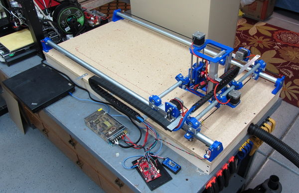
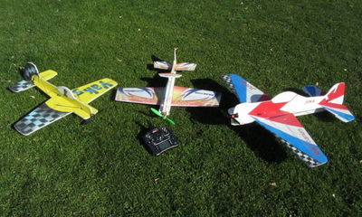
While "impressing" the neighborhood kids with some of my old 3D foamies (small, aerobatic foam RC planes) I decided to work on drawing some plans to help the kids build their own small flyers. Of course this led me down several paths. I first bought some foam board and hand cut a couple of fuselages modeled on an old DW Foamies Juka 40 3D plane. This proved to be a real pain so the next thing I looked into was how to build my own foam cutter that would be relatively inexpensive and easy to build.
|
So, while doing some googling on this I found an article from the great guys at Flightest RC about using an RC motor to drive a needle (like a sewing machine) for cutting foam and this article also led me to V1 Engineering who has some great ideas for a "Mostly Printed CNC" machine.
After all this (and much, much more) I decided how to proceed with my own version of a bench-top CNC for foam cutting and other jobs. This article then, is my version using an old 3D printer and ideas found in online articles and other resources.
NOTE: This machine is not and was never intended to be a metal cutting CNC mill. It is intended to be a lightweight engraver/ plotter/ foam cutter/ template cutter.
All designs found in this article are licensed under ![]() - Creative Commons Attribution-NonCommercial-ShareAlike 4.0 International
- Creative Commons Attribution-NonCommercial-ShareAlike 4.0 International
As-Built Machine Specifications
|
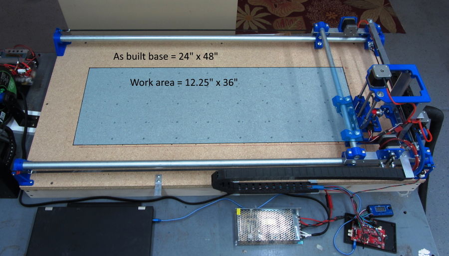
Some Numbers:
- Base Size - 24" x 48" x 13.5" (61cm x 122cm x 35cm)
- Base Width w/respect to Y axis = Y tube Length + 1/4" (6mm)
- Base Depth w/respect to X axis = X tube Length + 2" (51mm)
- Work Area - 12" x 36" x 3" (31cm x 63cm x 8cm)
- Max plot path w/respect to Y axis = Y tube length - 11" (280mm)
- Max plot path w/respect to X axis = X tube length - 9-1/2" (241mm)
- Control Board - Printrboard Rev D (from a very old 3D printer)
- Will be replaced with CNC board
- Number of Stepper motors - 4, 1 for X, 2 for Y, 1 for Z
- Stepper Motor Size - Nema 17, 45mmL w/4 wires
- Drive type - X and Y axis are GT2 belt drive, Z axis is by 8mm lead screw
- Number of 3D Prints - 24 (not including tool pieces)
- Total print time <60 hours
What to do with an Old 3D Printer
|
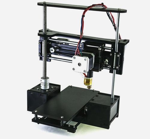
Because I had a very old OneUp 3D printer taking up space (in a box) I decided to use its components for a first shot at building my CNC. From this printer I took the below items. Prices shown are from random online searches (March 2020):
- 4 - Nema 17, 45mm, 4 wire stepper motors ($28)
- 3 - MakerBot style stop limit switches ($6)
- 1 - ATX 12v power supply ($16)
- 2 - 8mm x 15mm x 45mm slide bearings ($9)
- 2 - 8mm x 200mm guide rods, tapped to 4mm both ends (incl)
- 1 - PrintrBoard Rev D control board (CNC version $30)
- Total purchase cost ~$89
Added to this are the rest of the printer pieces found online:
- 6 - GT2 Pulleys with 5mm I.D. ball bearings ($8)
- 3 - GT2 20 tooth drive gears (incl)
- 1 - 5m GT2 belt ($6)
- 3 - GT2 belt spring clips (incl)
- 1 - 8mm x 5mm lead screw coupler ($8)
- 1 - 8mm x 2mm pitch x 200mm long lead screw ($11)
- 1 - 8mm x 2mm pitch lead screw nut (incl)
- Total purchase cost ~$33
- Total 3D printer parts used - $122
Printed Parts
|
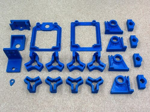
This section has information on the projects 3D print parts. In the list below, the column "Print File" has an STL download link (left click) to get the print file of each part.
| Image | Part Number | QTY | Part Description | Print File | Part Notes |
|
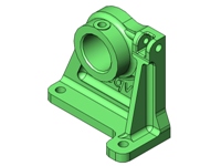
80001 | 1 | Corner Mount, Type A | 80001.STL | Print in ABS or PLA at 0.2mm resolution and 50% infill |
|
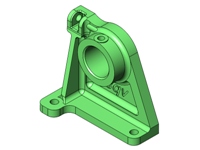
80002 | 2 | Corner Mount, Type B | 80002.STL | Print in ABS or PLA at 0.2mm resolution and 50% infill |
|
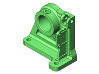
80003 | 1 | Corner Mount, Type C | 80003.STL | Print in ABS or PLA at 0.2mm resolution and 50% infill |
|
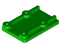
80004 | 1 | X-Axis Limit Switch Mount | 80004.STL | Print in ABS or PLA at 0.2mm resolution and 50% infill |
|
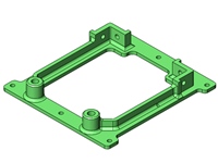
80005 | 1 | Tool Carriage Base Plate | 80005.STL | Print in ABS or PLA at 0.2mm resolution and 50% infill |
|
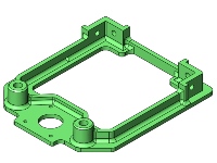
80006 | 1 | Tool Carriage Top Plate | 80006.STL | Print in ABS or PLA at 0.2mm resolution and 50% infill |
|
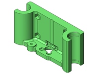
80007 | 1 | Z-Axis Slide Mount | 80007.STL | Print in ABS or PLA at 0.2mm resolution and 50% infill |
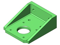
|
80008 | 1 | Tool Carriage Drive Mount | 80008.STL | Print in ABS or PLA at 0.2mm resolution and 50% infill |
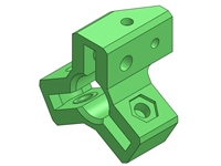
|
80009 | 2 | X-Axis Carriage Slide, A | 80009.STL | Print in ABS or PLA at 0.2mm resolution and 50% infill |
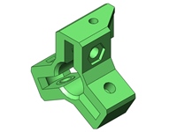
|
80010 | 2 | X-Axis Carriage Slide, B | 80010.STL | Print in ABS or PLA at 0.2mm resolution and 50% infill |
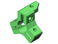
|
80011 | 2 | Y-Axis Gantry Slide, A | 80011.STL | Print in ABS or PLA at 0.2mm resolution and 50% infill |
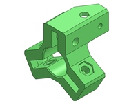
|
80012 | 2 | Y-Axis Gantry Slide, B | 80012.STL | Print in ABS or PLA at 0.2mm resolution and 50% infill |
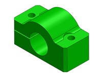
|
80013 | 4 | X-Axis Tube Clamp | 80013.STL | Print in ABS or PLA at 0.2mm resolution and 50% infill |
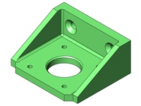
|
80014 | 2 | Gantry Drive Mount | 80014.STL | Print in ABS or PLA at 0.2mm resolution and 50% infill |
Specific Part Notes
- 80016, Needle Cutter Needle Holder is printed at 0.1mm resolution and 80% infill.
Printing Details and Times
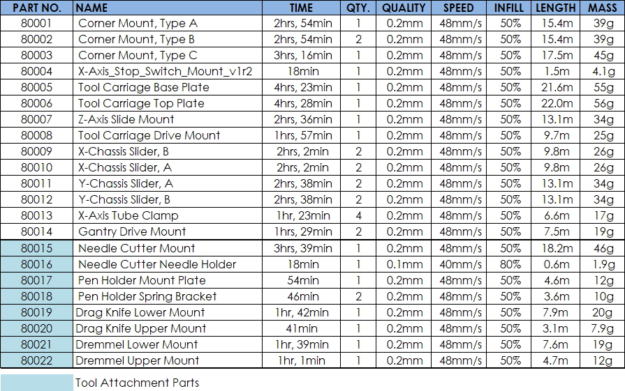
The chart below outlines print details with estimated print time and filament usage for the parts in this project.
Print filament used in first build:
- Hatchbox PLA, 1.75mm - ($22)
- Extruder Temp - 210C
- Bed Temp - 60C
|
The following is a summary of the machines parts only, no tool attachment parts:
- Total print time - 52hrs, 50min
- Total number of parts - 23
- Total filament used - ~0.76kg
Brackets & Turned Parts
|
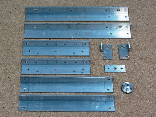
This section has information on aluminum parts made from standard hardware store materials. The column "Drawing File" has a PDF download link (right click and select save-as) to get the drawing details of each part. There are a total of 6 drawings describing these 12 parts which are listed by part number in numerical order.
| Image | Part Number | QTY | Part Description | Drawing File | As-built Mtl | Part Notes |
|
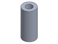
40001 | 2 | Spacer, 5mm x 10mm x 22mm | CNC004 | Aluminum tube - 3/8" x 0.049" wall | Aluminum spacer for the X-Axis cable track guide |
|
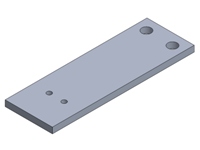
70001 | 1 | Y-Axis Cable Track Bracket, Base | CNC002 | Aluminum flatbar - 1" x 1/8" | Bracket to attach Y-Axis cable track to the wood base |
|
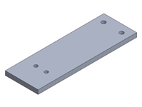
70002 | 1 | Y-Axis Cable Track Bracket, Gantry | CNC003 | Aluminum flatbar - 1" x 1/8" | Bracket to attach Y-Axis cable track to the Gantry |
|
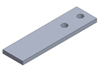
70003 | 2 | Cable Track Base Support Bracket | CNC002 | Aluminum flatbar - 3/4" x 1/8" | Bracket to support Y-Axis cable track |
|
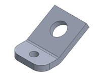
70004 | 2 | X-Axis Drive Belt Mount Bracket | CNC002 | Aluminum flatbar - 3/4" x 1/8" | Bracket to mount belt post |
|
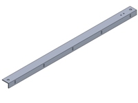
70005 | 1 | X-Axis Cable Track Support Bracket | CNC003 | Aluminum angle - 3/4" x 1/2" x 1/16" | Bracket to support X-Axis cable track |
|
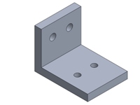
70006 | 1 | Tool Carriage Cable Track Mount Bracket | CNC002 | Aluminum angle - 1" x 1/8" | Bracket to mount X-Axis cable track to the tool carriage |
|
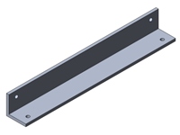
70007 | 2 | Tool Carriage Corner Bracket | 70007 | Aluminum angle - 1" x 1/8" | Corner post support bracket |
|
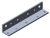
70008 | 2 | X-Axis Carriage Bracket | 70008 | Aluminum angle - 1" x 1/8" | X-Axis slide assembly bracket |
|
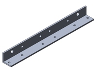
70009 | 2 | Y-Axis Gantry Bracket | 70009 | Aluminum angle - 1" x 1/8" | Y-Axis gantry slide assembly bracket |
|
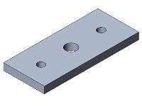
70010 | 1 | Needle Cutter Tip Mount Bracket | CNC002 | Aluminum flatbar - 3/4" x 1/8" | Bracket to mount the MIG weld tip |
|
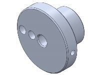
90001 | 1 | Needle Cutter Flywheel | CNC004 | Aluminum roundbar - 1" Dia. | Flywheel/crankshaft to drive the needle cutter |
Summary of purchased aluminum material used-
- Flat-bar - 3/4" x 1/8" x 12"L
- Flat-bar - 1" x 1/8" x 12"L
- Angle - 1" x 1" x 1/8" x 60"L
- Angle - 3/4" x 1/2" x 1/16" x 36"L
- Tube - 3/8" x 0.049 wall x 12"L
- Round-bar - 1" O.D. x 12"L
Specific Part Notes
Part and material substitutions are definitely OK. Here are two ideas-
- 40001 - Spacer, this part can be made from the material shown above or any close alternate like hard plastic tube.
- 90001 - Flywheel, This part can be made in many different ways including 3D printing. Here is a link to a 3D version - "Needle Foam Cutter for MPCNC"
Making Accurate Metal Parts
It is important on a project like this to get the dimensional accuracy of all parts as close as possible to avoid assembly and operational differences (problems). Below are details of how I do this on three of the critical parts without the benefit of using a vertical milling machine.
Tools & Miscellaneous
- Drill press++
- Sharp Center Punch
- Metric Drill Bits or # equivalents
- Avery #18665 Full Sheet Shipping Labels
- Computer and Printer
- PDF of 1:1 Layout Print
- Patience :)
++A powered hand drill can be substituted for the drill press if one is very skilled and careful.
Work Steps
- Step one - Download and print on regular paper the Layout Print linked below
- Layout Print PDF Link
- This needs to be printed with no scaling (at 100%). Now, using a scale or ruler, confirm that the lengths of each part shown on the print are accurate.
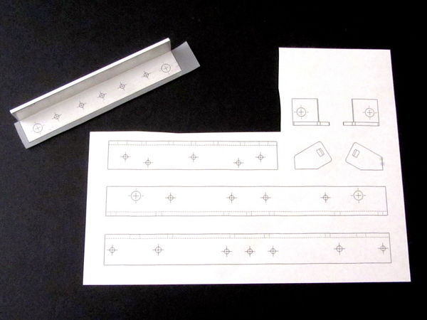
- Step two - Print the layout print on a sheet of the Avery shipping labels
- Step three - Carefully cut out the labels and apply them to the inside surfaces of the angle brackets as shown below:
|
| Cut and applied label |
- Step four - Using a sharp center punch, VERY CAREFULLY punch each center mark
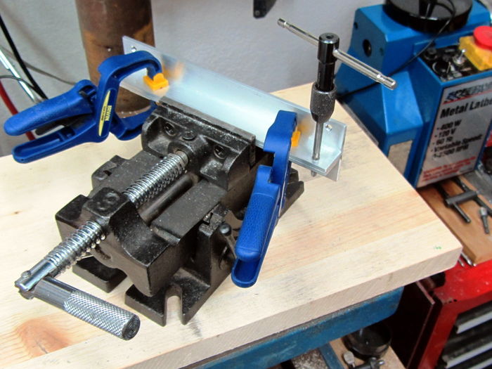
- Step five - With two ratchet clamps, clamp parts in pairs, put into a vise and drill each hole through both parts
- If any of the holes are tapped, do this while the parts are still clamped together in the vise
|
| Finishing the corner brackets |
- Step six - Lightly chamfer all holes and break all sharp edges
You should now have a set of very accurate parts ready to assemble!
Fasteners
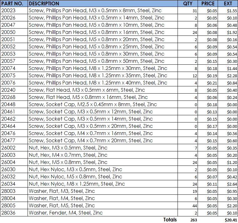
The chart below lists all the fasteners used on my first build. Part numbers and descriptions are from my own part database and prices shown are from BoltDepot.com as of April 2, 2020.
|
Design and Sub-Assemby
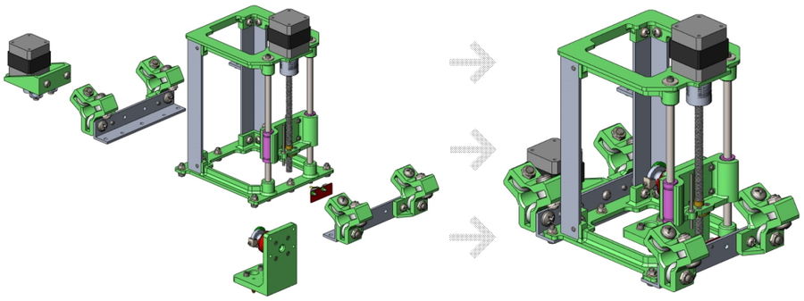
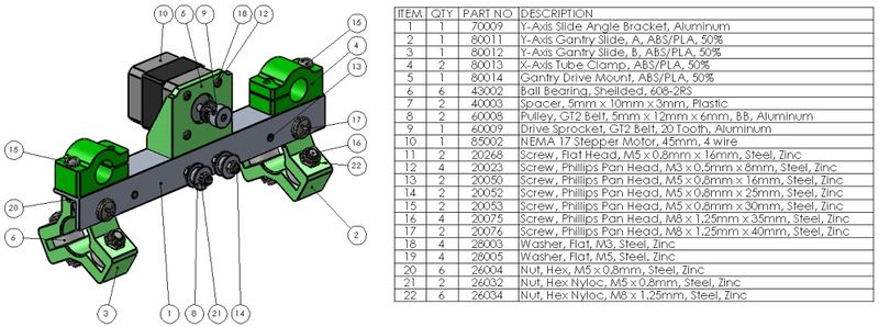
This section takes a look at some of the major sub assemblies and how they are intended to be built. All designed parts were done in SolidWorks and are licensed as "Share Alike, Non-Commercial".
One of the great ideas from the folks at V1 Engineering was to use metal conduit for the Y-axis and X-axis slides. The total cost for these pieces is around $18 and they were purchased from a local big box hardware store. The tube is called EMT Conduit or "Electric Metallic Tube (EMT) Conduit". If you go this route, make sure to check the pieces you buy for straightness and a consistent finish. After cutting to length I did sand the tubes with 220 and 400 grit sandpaper to get a nice smooth motion from the two gantries.
As an example, here is a link to one of the tubes (#60005 EMT Conduit Tubing, 1/2"):
- Link: EMT Conduit
The below link will get you a complete parts list. All part numbers shown are my own and have no relation to any existing manufacturers part. They are simply an easy way to reference each component.
- Link: CNC_Parts_v1.1.pdf
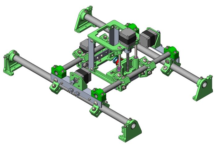
|
| Top assembly with Needle Cutter tool |
X-Axis Tool Carriage Slider
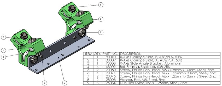
|
X-Axis Carriage Drive
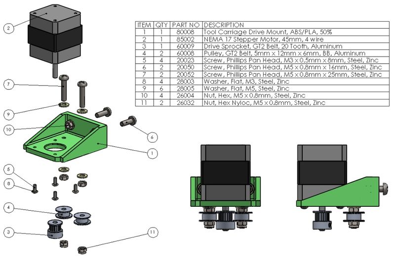
|
X-Axis Tool Carriage
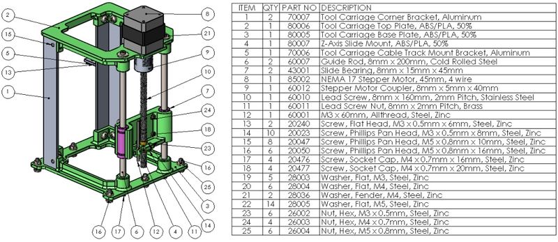
|
|
Y-Axis Gantry Slider
|
Base and Vacuum Table
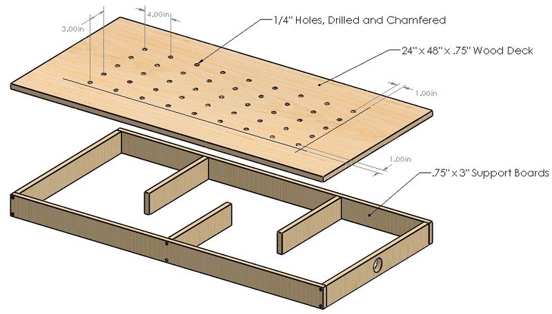
This is my "As-Built" base which includes structure for adding a shop vacuum to help secure the work piece. For the top I used a piece of HD Particle board and for the structure I used typical 1 x 3 White-wood found at the local big box store (Lowes). All structure pieces were ripped on a table saw to ~2.4" and the hole for my shop-vac was cut to 1-3/4" with a hole saw.
|
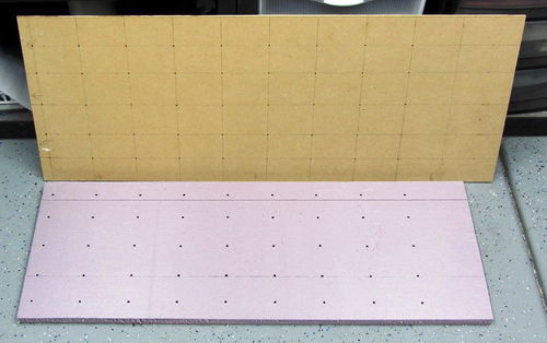
To drill the deck holes, I laid out the hole pattern on a piece of 1/4" hard-board, secured it in place on the deck piece against the X and Y axis (marked) and drilled through both. This gave me a template to use for making (purple) foam work support pieces which are needed when using the Needle Cutter. I simply place the template on top of a new piece of foam, lining up the two X and Y edges, and quickly hot-wire through each hole.
|
| Template and 3/4" purple foam piece |
Tool Attachments
|
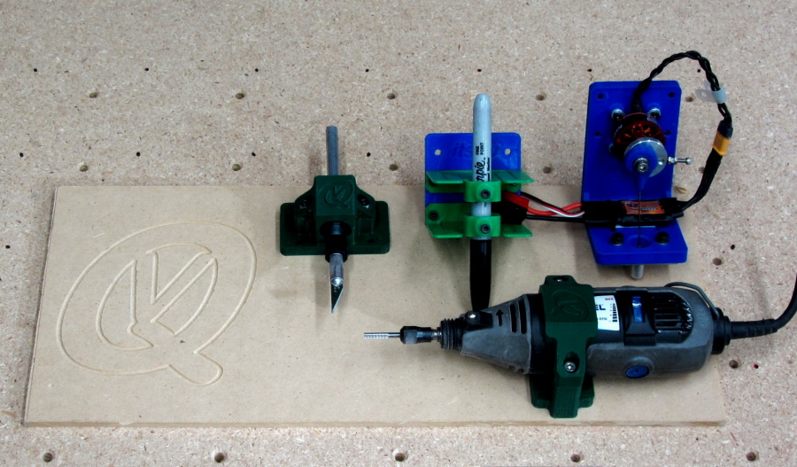
Tool attachments are what make this project! Here I show four different tools which all work very well and are all attached via four M4 socket head screws.
Needle Cutter Tool
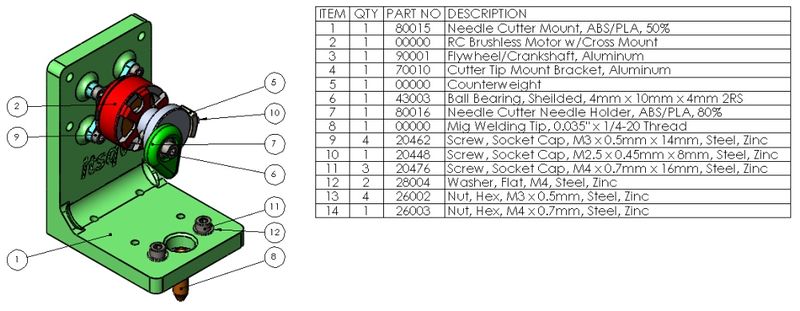
The Needle Cutter tool works really well for cutting foam panels. I got the idea from the great guys at Flightest RC and this in turn pointed me to a Thingiverse version of this tool. Here is the forum posts which have more info and many other ideas on how to do this - cutting-foam-sheets-with-a-needle.
|
While the design is simple enough, it is dependent on using a motor with exactly the same dimensions or the alignment over the needle guide hole will need to be adjusted. For a motor I chose one I already had, a Racerstar BR2508-1275kv. The motor configuration, with a threaded shaft, short stator and low 1275Kv was perfect for an application like this. This motor is powerful enough to handle just about any foam cutting you might need and it is still very small and light. The important dimension from the mount face to the end face is 23mm and the motor diameter is 32mm. To control the motor I am using a very inexpensive brushless speed control that is rated for 20A but a 10A would do just fine.
As far as the flywheel part, the forum link above will give you many options to use 3D printed pieces as opposed to the turned aluminum piece I made for mine.
The "MIG Tip" that guides the wire needle is a MIG welding tip you can find at big box or welding supply stores. I have used sizes from 0.035" to 0.047" with both weld wire needles and music wire needles. Both work well!
Pen Plotter Tool
The Pen Plotter tool is really just a pair of simple, light, spring brackets with screws to secure the pen. The pen tip will be close to the 0,0 point of the needle cutter but it is not exactly the same because its exact location depends on the pen diameter. Sharpies and roller ball pens work best.

|
To set it up, first zero the Z axis then raise the tool 0.5mm to 1mm. Next place the pen in the holder with the pen tip resting on the deck. Carefully tighten the clamp screws without moving the springs up or down. If your machine is stable and has a very flat deck, this should be enough "springiness" to draw a very clean image. If it skips in spots, reset the pen with a little more Z height.
Drag-Knife Tool
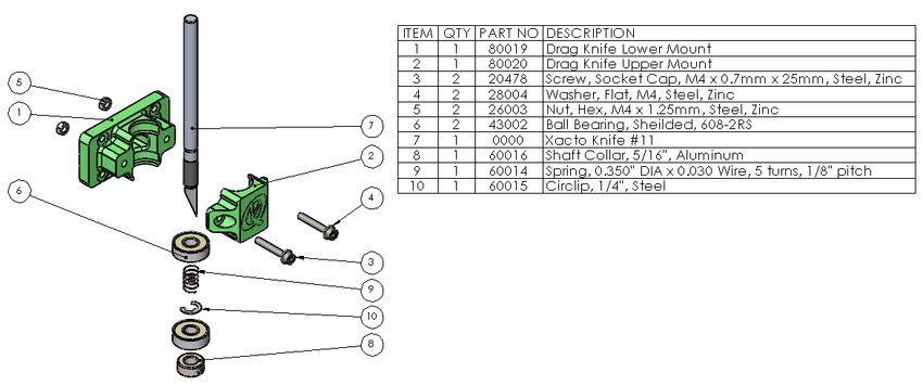
I wanted a way to cut decals and paint templates so I took a look at professional Drag Knives to get an idea and this is what I came up with. It is built with the same bearings I used in the CNC sliders, a spring for pre-load, an Xacto Knife and a couple of printed parts.
|
Dremmel Router Tool
Always wanted a way to do some engraving and I already had the Dremmel. This is just a simple clamp and because of the type of coupler I have on the lead screw, the cutter will move a small amount vertically. Even with the movement, it still does a very nice job on soft wood.
NOTE: There are many models of the Dremmel Tools! This clamp fits the "Dremmel MultiPro model 395"

|
Laser Engraving/Cutting Tool
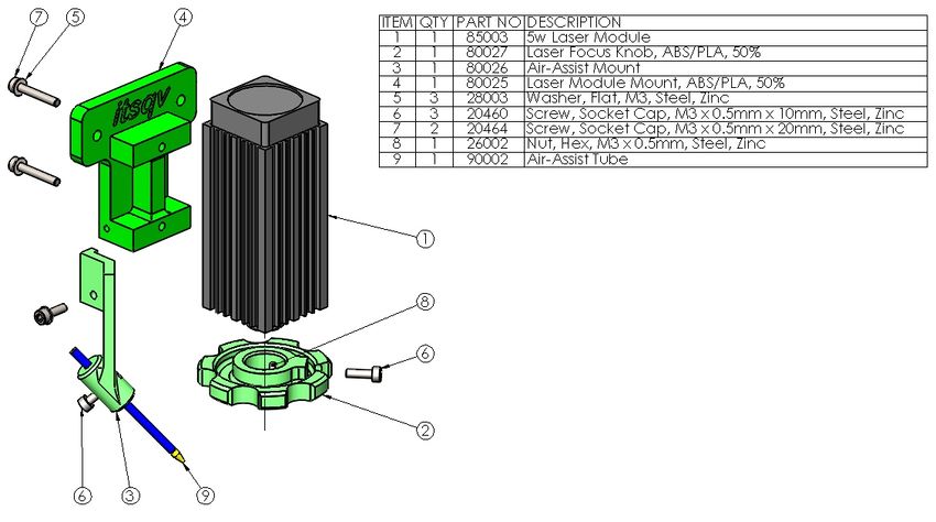
Always wanted a way to do some Laser engraving and cutting! I found an inexpensive, 5 watt Laser Module (On Sale - $89) and thought I would give it a try. I did a couple iterations of the mount and added an air-assist nozzle which made a huge difference in burn and cut quality
NOTE: These parts are designed specifically for the Banggood 5w Laser Module and likely will not fit other modules
|
Tool Print Parts
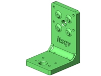
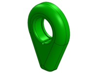
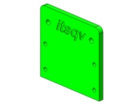
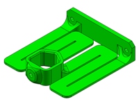
The following are print parts for the Needle Cutter Tool and the Plotter/Pen Holder Tool:
| Image | Part Number | QTY | Part Description | Print File | Part Notes |
|
80015 | 1 | Needle Cutter Mount | 80015.STL | Print in ABS or PLA at 0.2mm resolution and 50% infill |
|
80016 | 1 | Needle Cutter, Needle Holder | 80016.STL | Print in ABS or PLA at 0.1mm resolution and 80% infill |
|
80017 | 1 | Pen Holder Mount | 80017.STL | Print in ABS or PLA at 0.2mm resolution and 50% infill |
|
80018 | 2 | Pen Holder Spring Bracket | 80018.STL | Print in ABS or PLA at 0.2mm resolution and 50% infill |
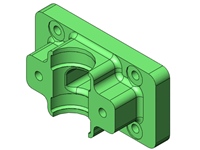
|
80019 | 1 | Drag Knife Lower Mount | 80019.STL | Print in ABS or PLA at 0.2mm resolution and 50% infill |
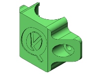
|
80020 | 1 | Drag Knife Upper Mount | 80020.STL | Print in ABS or PLA at 0.2mm resolution and 50% infill |
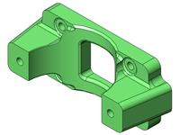
|
80021 | 1 | Dremmel Clamp Lower Mount | 80021.STL | Print in ABS or PLA at 0.2mm resolution and 50% infill |
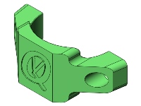
|
80022 | 1 | Dremmel Clamp Upper Mount | 80022.STL | Print in ABS or PLA at 0.2mm resolution and 50% infill |
|
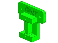
80025 | 1 | Laser Module Mount | 80025.STL | Print in ABS or PLA at 0.2mm resolution and 50% infill |
|
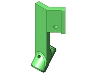
80026 | 1 | Air-Assist Nozzle Mount | 80026.STL | Print in ABS or PLA at 0.2mm resolution and 50% infill |
|
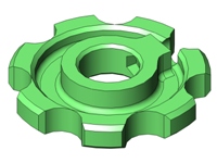
80027 | 1 | Laser Focus Knob | 80027.STL | Print in ABS or PLA at 0.2mm resolution and 50% infill |
Controls
This is a brief description of what I use to control the CNC. There are three control boards shown here, initial as-built 3D control board and two purpose built CNC control set-ups. I wanted to keep the cost low and the control system simple. To that end, all the systems here need a computer (laptop) to work. For a control user interface I am using the free Universal Gcode Sender (UGS) software linked below-
As-Built
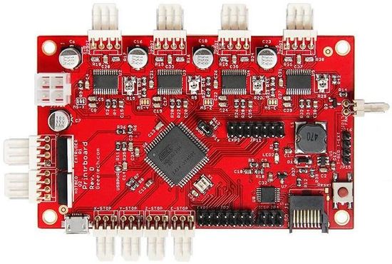
|
| Printrboard REV D |
As I stated in the introduction and the old printer section, my initial control board was out of a very old OneUp 3D printer. Of course, no control system this old will work without some tweaking.
The first issue with it was it was programmed with a build plate size limit of 100mm x 100mm which needed to be changed to 910mm x 310mm. The next issue was finding software/firmware that would allow me to make changes to the firmware. After a LOT of digging and trial and error I found an old link that amazingly still worked which offered the firmware and an old version of Arduino (0022) that would support and upload it.
After hours of fiddling, I finally got it modified and uploaded to the board. The next issue was getting the board to connect to either Pronterface or Repetier print software and this too took a lot of trial and error as both would connect but throw errors. The method that finally worked involved disconnecting stop switches and one stepper motor and powering up the board after connecting the USB. Then I connect the software and plug in the stop switches as well as the stepper motor.
The video at the end of this article shows the results which are pretty good! I will be changing to a proper CNC control board with more current software and plug-and-play functionality - Stay tuned!
Original 3018 CNC Board
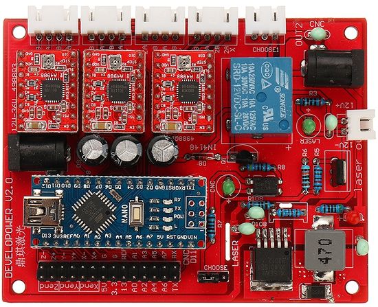
|
| 3018 CNC Board |
This board, which is labeled "Developower v2.0" did not work well for me. It was OK as long as I didn't attempt to activate the limit switches, something I feel is mandatory. I did download and install the most current stable firmware and I also swapped out the clone Arduino Nano with an original equipment one but neither the current firmware or the new Arduino board made any difference. I also tried changing out the Makerbot limit switches I was using with industrial Micro-Switch units and again, no change. At one point, when trying to activate the limit switches, it dumped all the machine eeprom settings and stopped working completely.
From here I did a little more research and came up with another inexpensive option (see below). In any case I would not recommend going with the 3018 CNC board.
SainSmart 3-Axis Control Board
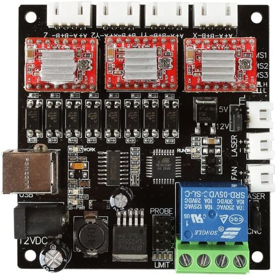
|
| SainSmart Board |
I found this board on Amazon but you can also get it direct from Sainsmart here: Sainsmart. I am really impressed! It worked right out of the box including limit switches and active homing. It was very easy to set-up and I now have a case printed up to help protect it. It has an on-board power relay to manage a spindle motor and a TTL capable Laser output/input.
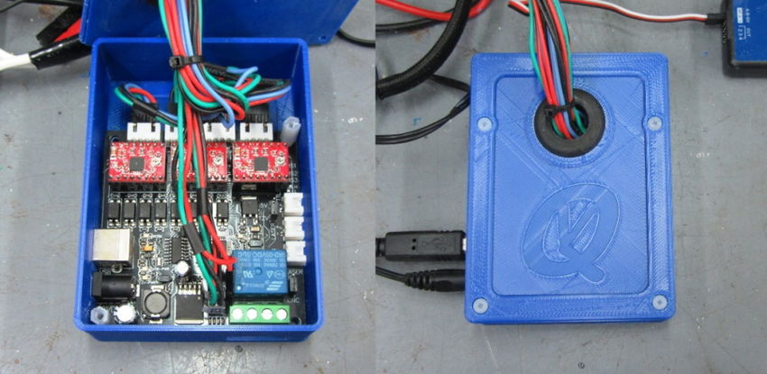
|
With a price of around $25, it is a great bargain.
Gallery
A few project pictures:
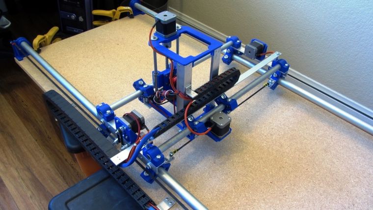
|
| Almost there! |
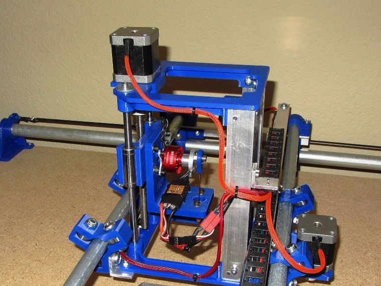
|
| Needle Cutter Tool |
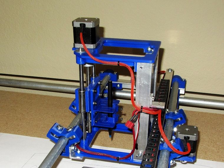
|
| Pen Plotter/Holder Tool |
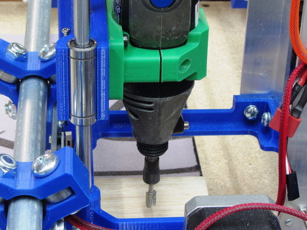
|
| Standard Dremmel Clamp |
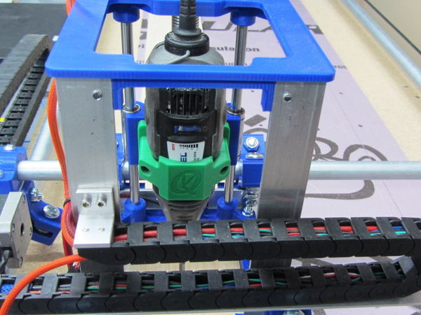
|
| Dremmel Clamp |
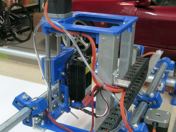
|
| 5w Laser Mount |
First Jobs Images and Video
Here are a few images of the first tasks completed on my CNC. I did the pen plot first to do a final check of the dimensional accuracy in X and Y of the parts to be cut. Hard to see because I used a fine point pen for the measurement accuracy. Once the X and Y dimensions are dialed in, it is on to cutting!
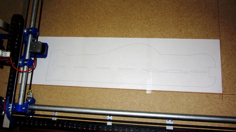
|
| Pen plot |
Next is the result of the first part set I cut out of 5mm Foam-Board (total cost - $4!). The fuselage parts are low density and the wing is high density. Cuts needed a very small amount of sanding to clean off paper remnants and to smooth out some very minor bumps.
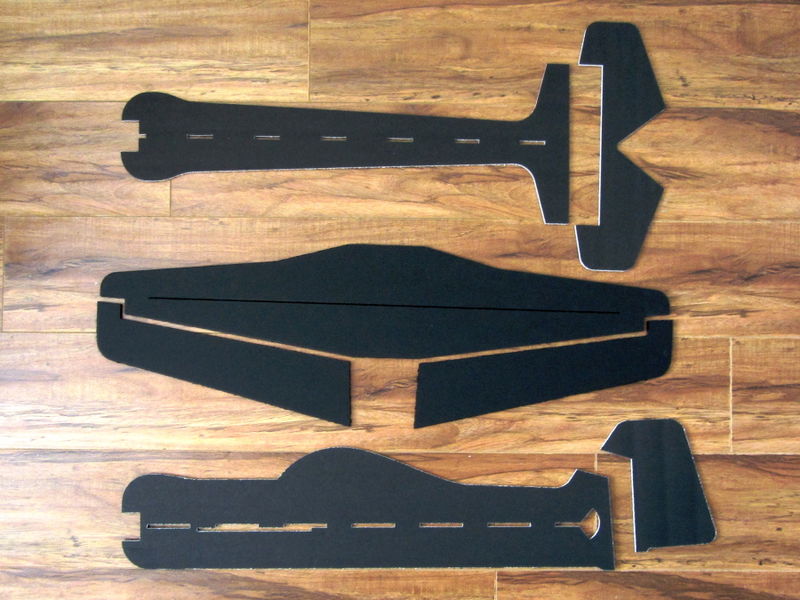
|
| First part set |
Here are the first parts all glued together and ready to go fly. Wingspan is 32" and total material cost is ~$4!!
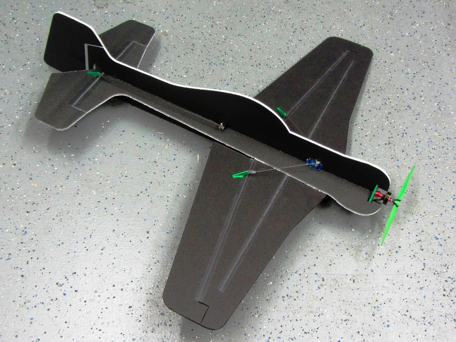
|
| First completed plane and a fantastic flyer! |
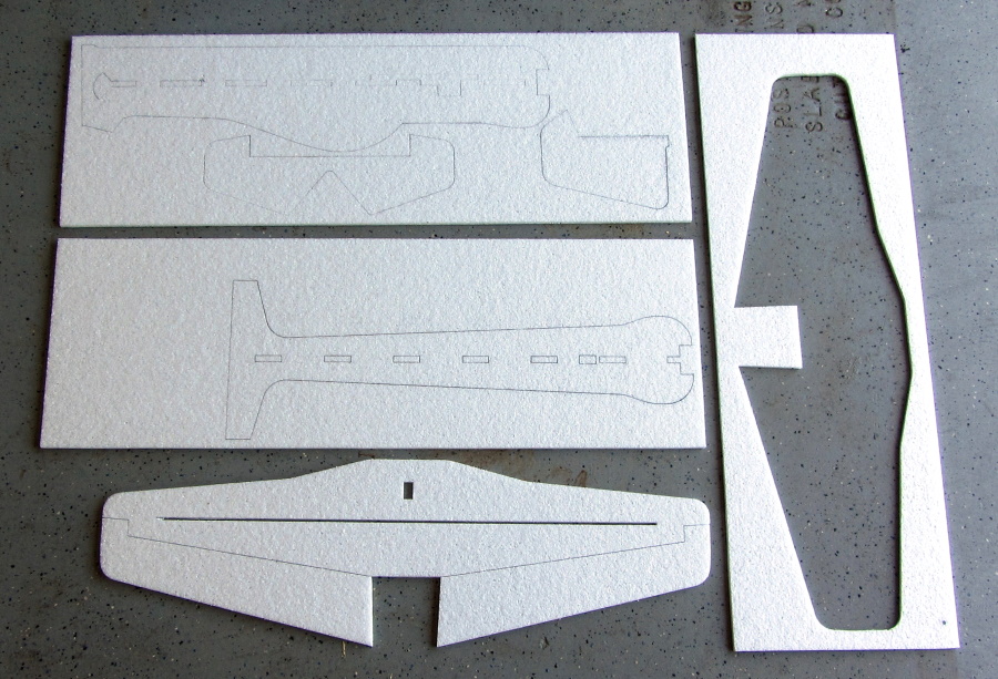
And now the Juka cut out in 1.9Lb EPP foam!
|
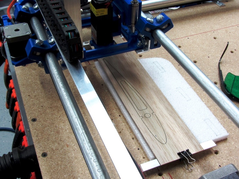
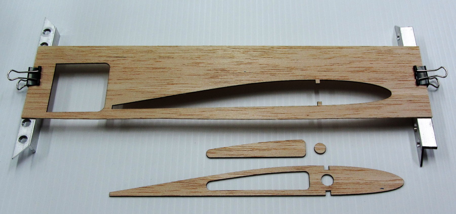
First laser cut part, a wing rib as a test piece which came out beautiful! Cut out of 1/16" balsa at 500mm/min and 4 passes.
|
|
First Cut Video!
|
First Cut! March 14, 2020 |
Updates!!
The Old Board
The Sainsmart board worked well until I started getting more serious with the laser. When I started cutting materials using multiple passes, I began to see slippage (lost steps) on the Y axis. First thing I did was replace the very old, very used steppers with new Stepperonline, 0.9deg motors. Well it ran smoother to more slippage. Next I tried changing out the A4898 drivers with TMC2208 drivers. This didn't work well as these TMC2208 drivers are not compatible with this particular Sainsmart board. At this point I came to the conclusion this board could use an upgrade.
New Board
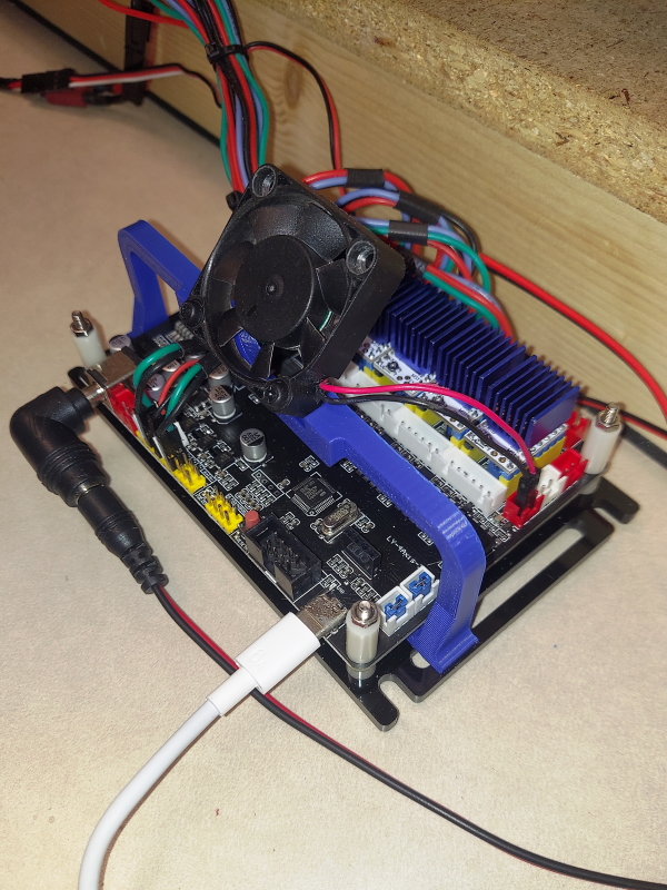
This new board is made or distributed by a company called "Annoytools". It is a 4 axis board with two drives for the two Y axis motors (nothing shared). It is a 32bit card with a USB-C interface and needs 24v to run. Since I already bought the TMC2208 drivers I put these in and reset the vref.
It is super quiet now and very smooth running but there is still an issue with the Y-axis accuracy.
|
| New Board! |
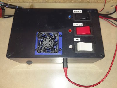
|
| New Case! |
Y-axis Accuracy SOLVED!
Turns out some components are better than others! While I was (again) checking all the mechanicals for problems that might contribute to the Y-axis issue, I discovered the Y-axis belts would slip a very small amount on the motor drive pulley. In doing a little online research I found lots of info on this issue and the overwhelming solution was to use Gates brand belts and pulleys. I also found a few references to belt width. With this new info, I found a US supplier who sells the Gates belts and pulleys in a 9mm width so I changed the two Y-axis belts and pulleys to this wider belt. I also changed the X-axis belt to Gates as well, keeping this one at 6mm width. BINGO! I can happily report the the machine is now incredibly accurate in both the X and Y axis.
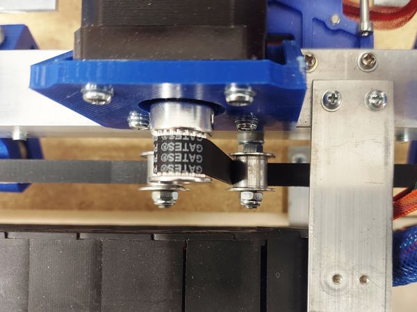
|
| Quality matters! |
Air Assist
Been constantly changing the air assist nozzle and this is my latest:
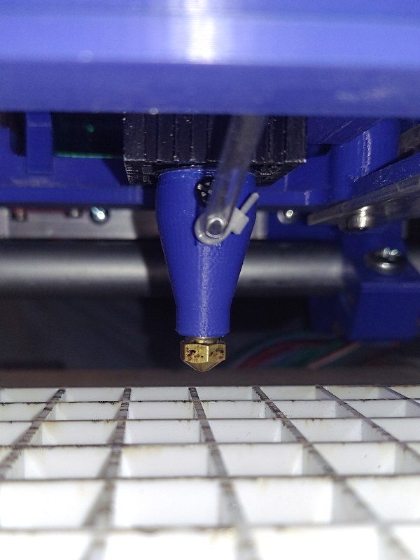
|
| Jet Power |
I used an old brass 3D printer nozzle tip as the sharp edge hole helps with the air jet. In addition to this I added a 12v air solenoid and an air pressure regulator set at about 9 psi. The solenoid is triggered on with the laser using the Spindle Speed output from the new board.
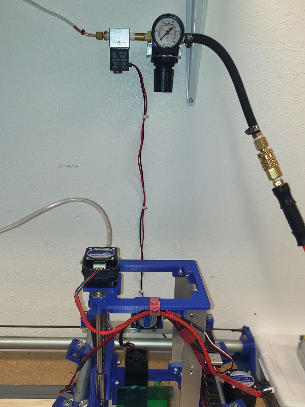
|
New Laser Module
The original laser module I was using was very low power and while it would cut 1/16" (1.6mm) balsa, it was really slow. I also had to do multiple passes on anything thicker than this. So I started looking around and found a relatively inexpensive ($135) unit that claimed it was a true 10 watt (optical) laser and would cut 1/4" balsa in a single pass. I thought this could be just marketing but I gave it a shot as I knew I could return it.
What a difference!
I can now cut 1/16" plywood in a single pass at nearly 6 times the speed over the old laser and at 50% power! I can also report it will cut 1/4" (6.3mm) balsa easily in a single pass!!
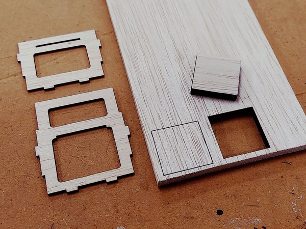
|
| 1/16" & 1/4" - No problem! |
To see the unit I purchased, follow the link below. Note that in this listing you have to select the 10w version.
- Link- Cronos 80w/10w Laser
New Look
This project has undergone extensive changes over the years and below is a picture of the carriage assembly on April 1st, 2024. I will be writing an updated version of this page with all the current parts and updates. Stay tuned!
Some changes!
As shown I abandoned the original carriage in favor of a build utilizing extruded aluminum rails running on Delrin wheels which makes things that much smoother. I also used an inexpensive, manual, Z axis slide mount which I modified with a stepper motor and manual knob. All this has made for an easier to use set-up which still allows the use of the other cutting, engraving and plotting tools shown above.

|
| Much cleaner! |
Acknowledgements
Inspiration for some of the ideas in this proect came from the following excellent sources:
- Pen holder for Shapeoko CNC
- by EGoe March 01, 2014
- V1 Engineering - Mostly Printed CNC
- Needle Cutter Information
- A great article by jhitesman on Instuctables Workshop
- -same author -
See Also
Info
Downloads
- Complete "As-Built" parts list: CNC_Parts_v1.1.pdf
- 3D Print Package: CNC_3D_Print_Package_v1.1.zip
- Aluminum Parts Drawing Package CNC_Drawings_v1.1.zip
- Aluminum Brackets Layout Label Sheet: Layout Print PDF
Vendors
Other DIY Projects