Difference between revisions of "DIY - Vacuum Forming Box"
(→Base Build) |
(→See Also) |
||
| (39 intermediate revisions by the same user not shown) | |||
| Line 3: | Line 3: | ||
{| cellspacing="1" cellpadding="1" width="95%" border="0" | {| cellspacing="1" cellpadding="1" width="95%" border="0" | ||
|- | |- | ||
| − | | align="left" valign=" | + | | align="left" valign="top" width="30%" | __TOC__ |
| align="right" width="70%" | [[File:VF01.JPG|700px]] | | align="right" width="70%" | [[File:VF01.JPG|700px]] | ||
|- | |- | ||
| Line 16: | Line 16: | ||
=== Tools I Used === | === Tools I Used === | ||
| − | Besides the basic hand tools, these | + | Besides the basic hand tools, these tools helped immensely with keeping things sized and squared perfectly. |
<br> | <br> | ||
| Line 22: | Line 22: | ||
:2. Drill press | :2. Drill press | ||
:3. 10" Table saw | :3. 10" Table saw | ||
| − | <br><br> | + | :4. Picture frame clamps |
| + | <br> | ||
| + | |||
| + | === Specifications === | ||
| + | |||
| + | :{| border="0" cellspacing="1" cellpadding="1" width="800" align="left" | ||
| + | |- | ||
| + | | width="110" align="left" | Forming Deck | ||
| + | | align="left" | 8" x 10" | ||
| + | |- | ||
| + | | align="left" | Sheet Size | ||
| + | | align="left" | 9-1/2" x 11-1/2" | ||
| + | |- | ||
| + | | align="left" | Dimensions | ||
| + | | align="left" | 12-3/4" x 25-1/4" x 5-1/2" | ||
| + | |- | ||
| + | | align="left" | Watts | ||
| + | | align="left" | 1000 | ||
| + | |} | ||
| + | <br clear=all><br> | ||
=== Parts & Pieces === | === Parts & Pieces === | ||
| − | Here is the complete parts list for this project. All dimensions and screw specs for this project are imperial (inches). | + | Here is the complete parts list for this project. All dimensions and screw specs for this project are imperial (inches). The dimensions for the wood cut pieces are based on perfectly sized wood so if you copy this you will need to make adjustments based on the wood you select. |
<br> | <br> | ||
'''Cut List'''<br> | '''Cut List'''<br> | ||
| − | : Hardwood 3/4 x 2-3/4 x 11-1/2 | + | :{| border="0" cellspacing="1" cellpadding="1" width="800" align="left" |
| − | + | |- | |
| − | + | | width="15" align="left" | 2x | |
| − | + | | align="left" | Hardwood 3/4 x 2-3/4 x 11-1/2 | |
| − | + | |- | |
| − | + | | align="left" | 2x | |
| − | + | | align="left" | Hardwood 3/4 x 3-1/4 x 24 | |
| − | + | |- | |
| − | + | | align="left" | 2x | |
| − | + | | align="left" | Hardwood 3/4 x 3-1/4 x 11-1/2 | |
| − | + | |- | |
| − | + | | align="left" | 2x | |
| − | + | | align="left" | Hardwood 5/8 x 1-1/2 x 2 | |
| − | + | |- | |
| − | + | | align="left" | 2x | |
| − | + | | align="left" | Hardwood 3/4 x 2-3/4 x 10 | |
| − | <br> | + | |- |
| + | | align="left" | 1x | ||
| + | | align="left" | Hardwood 3/4 x 2-3/4 x 10-1/8 | ||
| + | |- | ||
| + | | align="left" | 1x | ||
| + | | align="left" | Plywood 1/4 x 11-1/2 x 24 | ||
| + | |- | ||
| + | | align="left" | 1x | ||
| + | | align="left" | Plywood 1/4 x 11-1/2 x 14 | ||
| + | |- | ||
| + | | align="left" | 1x | ||
| + | | align="left" | Pine Laminate 1 x 8 x 10 | ||
| + | |- | ||
| + | | align="left" | 2x | ||
| + | | align="left" | Alum Flatbar 1/8 x 1 x 3-1/2 | ||
| + | |- | ||
| + | | align="left" | 2x | ||
| + | | align="left" | Alum Angle 1/16 x 1/2 x 1/2 x 14L | ||
| + | |- | ||
| + | | align="left" | 2x | ||
| + | | align="left" | Alum Angle 1/16 x 1/2 x 1/2 x 10-1/2L | ||
| + | |- | ||
| + | | align="left" | 2x | ||
| + | | align="left" | Alum Angle 1/16 x 1/2 x 1/2 x 9-1/2L | ||
| + | |- | ||
| + | | align="left" | 2x | ||
| + | | align="left" | Alum Angle 1/16 x 1/2 x 1/2 x 11-1/4L | ||
| + | |- | ||
| + | | align="left" | 1x | ||
| + | | align="left" | Wood Dowel 1/2D x 10-1/2L | ||
| + | |- | ||
| + | | align="left" | 1x | ||
| + | | align="left" | Galvanized Sheet Metal, 30ga, 16 x 14 | ||
| + | |} | ||
| + | <br clear=all> | ||
'''Hardware'''<br> | '''Hardware'''<br> | ||
| − | : 4x #8 x 1-1/4" wood Screws | + | :{| border="0" cellspacing="1" cellpadding="1" width="800" align="left" |
| − | + | |- | |
| − | + | | width="15" align="left" | 4x | |
| − | + | | align="left" | #8 x 1-1/4" wood Screws | |
| − | + | |- | |
| − | + | | align="left" | 14x | |
| − | + | | align="left" | #4 x 3/4" wood screws | |
| − | + | |- | |
| − | + | | align="left" | 4x | |
| − | + | | align="left" | #8-32 x 2" round head machine screws | |
| − | + | |- | |
| − | + | | align="left" | 5x | |
| − | + | | align="left" | #8-32 x 1" pan head machine screws | |
| + | |- | ||
| + | | align="left" | 20x | ||
| + | | align="left" | #6-32 x 3/8" flat head machine screws | ||
| + | |- | ||
| + | | align="left" | 8x | ||
| + | | align="left" | #6-32 x 3/8" pan head machine screws | ||
| + | |- | ||
| + | | align="left" | 2x | ||
| + | | align="left" | #12-24 x 3/4" button head machine screws | ||
| + | |- | ||
| + | | align="left" | 9x | ||
| + | | align="left" | #8-32 hex nuts | ||
| + | |- | ||
| + | | align="left" | 28x | ||
| + | | align="left" | #6-32 hex nuts | ||
| + | |- | ||
| + | | align="left" | 2x | ||
| + | | align="left" | #12 nylok hex nuts | ||
| + | |- | ||
| + | | align="left" | 14x | ||
| + | | align="left" | #8 flat washers | ||
| + | |- | ||
| + | | align="left" | 2x | ||
| + | | align="left" | 3/16 x 3/8 x 3/16 nylon spacers | ||
| + | |- | ||
| + | | align="left" | 8x | ||
| + | | align="left" | small steel flat corner brackets | ||
| + | |- | ||
| + | | align="left" | 5x | ||
| + | | align="left" | 3/16 x 1/2 x 3/8L phenolic spacers | ||
| + | |- | ||
| + | | align="left" | 4x | ||
| + | | align="left" | 1/2 x 5/8D rubber feet w/screws | ||
| + | |- | ||
| + | | align="left" | 10x | ||
| + | | align="left" | 3/4" binder (spring) clips | ||
| + | |} | ||
| + | <br clear=all> | ||
| + | |||
| + | '''Heater Components'''<br> | ||
| + | : [https://www.walmart.com/ip/Mainstays-4-Slice-Toaster-Oven-Black/53986434?wmlspartner=wlpa&selectedSellerId=0&adid=22222222227048244851&wl0=&wl1=g&wl2=c&wl3=146907660229&wl4=pla-258903087109&wl5=9030743&wl6=&wl7=&wl8=&wl9=pla&wl10=8175035&wl11=online&wl12=53986434&wl13=&veh=sem Walmart Toaster Oven] | ||
| + | ::If you live where the power is 220v look for a toaster oven that is 800 - 1000 watts with two elements. | ||
| + | <br><br> | ||
| + | |||
| + | == The Build == | ||
| + | |||
| + | === First Things First === | ||
| + | |||
| + | '''Toaster Oven'''<br> | ||
| + | |||
| + | While reading many articles on how to create an effective heating element I found a YouTube video from a guy who was simply using a toaster oven to heat the plastic in an aluminum frame. So, I bought a toaster oven at Wallmart for $19 and gave this method a try. I found that these heating elements provided more than enough heat for this purpose so I incorporated the heat elements and the complete oven control system in my design. | ||
<br> | <br> | ||
| − | + | {| border="0" cellspacing="1" cellpadding="1" width="800" align="center" | |
| − | : | + | |- |
| + | | align="center" | [[File:VF05.JPG|600px]] | ||
| + | |- | ||
| + | | align="center" | WallMart toaster oven | ||
| + | |} | ||
<br><br> | <br><br> | ||
| − | + | ||
=== Base Build === | === Base Build === | ||
| + | |||
| + | I started with the wood box. Using the 10" Chop saw I could make the corners nearly perfectly square which is a big plus. | ||
| + | <br> | ||
{| border="0" cellspacing="1" cellpadding="1" width="800" align="center" | {| border="0" cellspacing="1" cellpadding="1" width="800" align="center" | ||
| Line 76: | Line 187: | ||
| align="center" | Cut wood pieces and box build | | align="center" | Cut wood pieces and box build | ||
|} | |} | ||
| + | <br> | ||
| + | |||
| + | I had a set of picture frame corner clamps which make the set-up and alignment of the corners super easy and solid. | ||
<br> | <br> | ||
| Line 84: | Line 198: | ||
| align="center" | Corner clamps | | align="center" | Corner clamps | ||
|} | |} | ||
| + | <br> | ||
| + | |||
| + | After the four corners were complete, I set everything else up and glued them all in with clamps to hold it all in place. | ||
<br> | <br> | ||
| Line 92: | Line 209: | ||
| align="center" | Box build | | align="center" | Box build | ||
|} | |} | ||
| + | <br> | ||
| + | |||
| + | With the box completed I then needed to put the two top pieces together and drill the vacuum deck. | ||
<br> | <br> | ||
| Line 100: | Line 220: | ||
| align="center" | Box and top parts | | align="center" | Box and top parts | ||
|} | |} | ||
| + | <br> | ||
| + | |||
| + | I laid out the hole pattern on my computer and printed a template that I used to center-mark the holes. | ||
<br> | <br> | ||
| Line 111: | Line 234: | ||
=== Frame Build === | === Frame Build === | ||
| + | |||
| + | The two frames are pretty basic builds. Using the chop saw with the 60 tooth carbide blade I first cut to length the for main frame pieces then cut the four mitered pieces for the clamp frame. | ||
| + | <br> | ||
{| border="0" cellspacing="1" cellpadding="1" width="800" align="center" | {| border="0" cellspacing="1" cellpadding="1" width="800" align="center" | ||
|- | |- | ||
| − | | align="center" | [[File:VF21.JPG| | + | | align="center" | [[File:VF21.JPG|600px]] |
|- | |- | ||
| − | | align="center" | | + | | align="center" | Aluminum frame components |
|} | |} | ||
<br> | <br> | ||
| − | + | The clamp frame then required four holes at each corner with the flat side or the aluminum angle being counter sunk to fit the #6-32 x 3/8 screws. | |
| + | <br> | ||
| + | |||
| + | {| border="0" cellspacing="1" cellpadding="1" width="800" align="center" | ||
| + | |- | ||
| + | | align="center" | [[File:VF22.JPG|600px]] | ||
| + | |- | ||
| + | | align="center" | Clamp frame corner detail | ||
| + | |} | ||
| + | <br> | ||
| + | |||
| + | The main frame was put together using corner brackets made from the flat corner brackets I had on hand. These have three holes in each bracket and I used #6-32 flat head screws on the inside flat surface. The two outside screws are #6-32 x 3/8 pan head screws. | ||
| + | <br> | ||
| + | |||
| + | {| border="0" cellspacing="1" cellpadding="1" width="800" align="center" | ||
| + | |- | ||
| + | | align="center" | [[File:VF23.JPG|600px]] | ||
| + | |- | ||
| + | | align="center" | Main frame joint detail | ||
| + | |} | ||
| + | <br> | ||
| + | |||
| + | I then cut a section of the 1/2" dowel stock for the handle and mounted it with a wood screw on each end. | ||
| + | <br> | ||
| + | |||
| + | {| border="0" cellspacing="1" cellpadding="1" width="800" align="center" | ||
| + | |- | ||
| + | | align="center" | [[File:VF24.JPG|600px]] | ||
| + | |- | ||
| + | | align="center" | Completed frames | ||
| + | |} | ||
| + | <br> | ||
| + | |||
| + | The completed frames held together with the 10 binder clips. | ||
| + | <br> | ||
| + | |||
| + | {| border="0" cellspacing="1" cellpadding="1" width="800" align="center" | ||
| + | |- | ||
| + | | align="center" | [[File:VF25.JPG|700px]] | ||
| + | |- | ||
| + | | align="center" | Completed and mounted frames | ||
| + | |} | ||
<br><br> | <br><br> | ||
=== Heat Box Build === | === Heat Box Build === | ||
| + | |||
| + | The heater box is made from thin galvanized sheet metal that I found in the air duct section of my local hardware store (Lowes). I layed it out and cut it with small metal shears after drilling all the corner and mount holes. | ||
| + | <br> | ||
{| border="0" cellspacing="1" cellpadding="1" width="800" align="center" | {| border="0" cellspacing="1" cellpadding="1" width="800" align="center" | ||
| Line 129: | Line 299: | ||
| align="center" | [[File:VF31.JPG|700px]] | | align="center" | [[File:VF31.JPG|700px]] | ||
|- | |- | ||
| − | | align="center" | | + | | align="center" | Sheetmetal layout and cut |
|} | |} | ||
<br> | <br> | ||
| − | + | I bent it using a couple of boards and the floor. This sheet metal is thin enough to bend by hand and finish by taping with a wood piece. | |
| + | <br> | ||
| + | |||
| + | {| border="0" cellspacing="1" cellpadding="1" width="800" align="center" | ||
| + | |- | ||
| + | | align="center" | [[File:VF32.JPG|700px]] | ||
| + | |- | ||
| + | | align="center" | Completed heat box | ||
| + | |} | ||
| + | <br> | ||
| + | |||
| + | After the box was bent and screwed together, I opened up the four holes and mounted the heater elements. I used the mount plates from the Toaster oven. | ||
| + | <br> | ||
| + | |||
| + | {| border="0" cellspacing="1" cellpadding="1" width="800" align="center" | ||
| + | |- | ||
| + | | align="center" | [[File:VF33.JPG|700px]] | ||
| + | |- | ||
| + | | align="center" | Heat element mount detail | ||
| + | |} | ||
<br><br> | <br><br> | ||
| − | == First | + | == First Vacu-Form! == |
| + | |||
| + | So, for a first try I used a spare 3D printed canopy for one of my Mini Talons. This part is large, has a complex surface with bumps, holes, air vents and some writing on the vertical surfaces. | ||
| + | <br> | ||
| + | |||
| + | To start I mount a piece of .020 PETG sheet between the frames place the mold piece on the vacuum deck. I then turn on the shop vac and then the heater and wait for the plastic sheet to sag about an inch in the center. | ||
| + | <br> | ||
{| border="0" cellspacing="1" cellpadding="1" width="800" align="center" | {| border="0" cellspacing="1" cellpadding="1" width="800" align="center" | ||
| Line 144: | Line 339: | ||
| align="center" | Wait for it! | | align="center" | Wait for it! | ||
|} | |} | ||
| + | <br> | ||
| + | |||
| + | Once the plastic has sagged enough, I flip the frame over the mold. The plastic sheet immediately forms over the mold and I shut off the heater and vacuum. | ||
<br> | <br> | ||
| Line 152: | Line 350: | ||
| align="center" | What's that sucking sound? | | align="center" | What's that sucking sound? | ||
|} | |} | ||
| + | <br> | ||
| + | |||
| + | The results of this first piece are excellent! Once parted and cleaned up, it is a perfect match. | ||
<br> | <br> | ||
| Line 160: | Line 361: | ||
| align="center" | A very light, near perfect replacement part! | | align="center" | A very light, near perfect replacement part! | ||
|} | |} | ||
| + | <br><br> | ||
| + | |||
| + | === Mods === | ||
| + | 22 June, 2018<br> | ||
| + | I added a limit switch that controls when the heaters are on. This is coupled to a small relay to handle the higher current of the heaters. The switch functons to only allow the heaters to heat when the frame is down over the heaters and to turn the heaters off when the frame and plastic are flipped over to the vacuum side.<br><br> | ||
| + | |||
| + | The switch is an SPDT micro switch with a straight lever I could bend to reach the frame - | ||
<br> | <br> | ||
| − | + | {| border="0" cellspacing="1" cellpadding="1" width="800" align="center" | |
| + | |- | ||
| + | | align="center" | [[File:VF72.JPG|600px]] | ||
| + | |} | ||
| + | <br> | ||
| + | |||
| + | The relay is a DPDT unit with 30A contacts and a 120v coil - | ||
| + | <br> | ||
| + | |||
| + | {| border="0" cellspacing="1" cellpadding="1" width="800" align="center" | ||
| + | |- | ||
| + | | align="center" | [[File:VF71.JPG|600px]] | ||
| + | |} | ||
| + | <br> | ||
| + | |||
| + | {| border="0" cellspacing="1" cellpadding="1" width="800" align="center" | ||
| + | |- | ||
| + | | align="center" | [[File:VF74.JPG|700px]] | ||
| + | |} | ||
<br><br> | <br><br> | ||
| − | + | '''Switch Parts:'''<br> | |
| + | : Switch - <u>[https://www.zoro.com/honeywell-premium-mini-swch-3a-spdt-lng-strt-lever-v7-2b17d8-048/i/G4550217/ Switch, Straight Lever, SPDT, 3A, 250VAC]</u> | ||
| − | + | : Relay - <u>[https://www.amazon.com/gp/product/B01NAXIBKB/ref=oh_aui_detailpage_o01_s00?ie=UTF8&psc=1 Omron LY2-UA-006244 Relay, DPDT, 30A, 120VAC]</u> | |
<br><br> | <br><br> | ||
| − | [[Category: | + | === Next! === |
| + | |||
| + | Next up I will look into creating plaster molds of some of the skids and wing protection parts I have made with other methods. | ||
| + | <br><br> | ||
| + | |||
| + | == See Also == | ||
| + | <br> | ||
| + | |||
| + | :* [[Current Parts Catalogs]] | ||
| + | :* [[DIY - Battery Pack Spot Welder]] | ||
| + | :* [[DIY - Dynamic Motor and Prop Balancer]] | ||
| + | :* [[DIY - Motor and Prop Test Bench]] | ||
| + | :* [[DIY - Vacuum Forming Box]] | ||
| + | |||
| + | <br><br><br> | ||
| + | |||
| + | [[Category:Contents]] | ||
Latest revision as of 15:06, 6 January 2023
© Mark Qvale - June, 2018
| |
| New DIY Tool |
Introduction
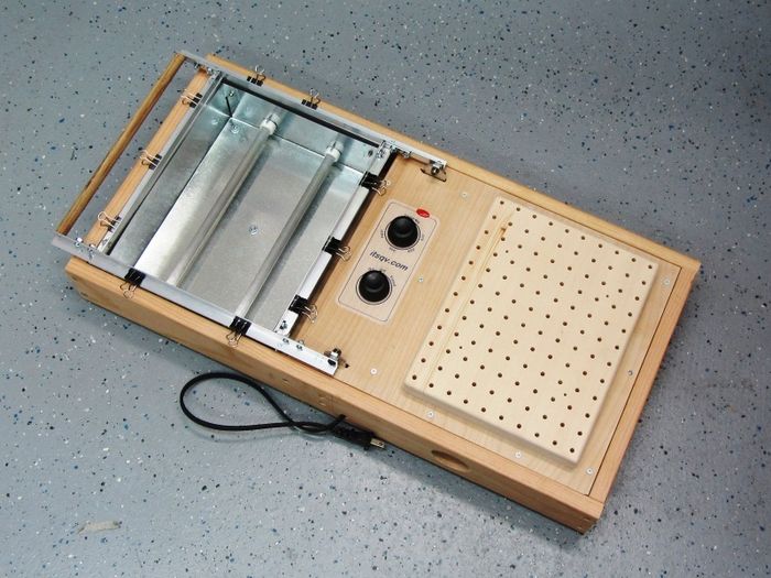
After doing hundreds of 3D prints for canopies, skids, shields, et., I decided to build my own Vacuum Forming box so I could get the weight dramatically down on some these parts. I did a pile of research and found many different styles and sizes but finally decided to simply take the things I liked in many pictures found on google and design my own. This then is my version.
Tools I Used
Besides the basic hand tools, these tools helped immensely with keeping things sized and squared perfectly.
- 1. 10" Chop saw w/60 tooth carbide blade
- 2. Drill press
- 3. 10" Table saw
- 4. Picture frame clamps
Specifications
Forming Deck 8" x 10" Sheet Size 9-1/2" x 11-1/2" Dimensions 12-3/4" x 25-1/4" x 5-1/2" Watts 1000
Parts & Pieces
Here is the complete parts list for this project. All dimensions and screw specs for this project are imperial (inches). The dimensions for the wood cut pieces are based on perfectly sized wood so if you copy this you will need to make adjustments based on the wood you select.
Cut List
2x Hardwood 3/4 x 2-3/4 x 11-1/2 2x Hardwood 3/4 x 3-1/4 x 24 2x Hardwood 3/4 x 3-1/4 x 11-1/2 2x Hardwood 5/8 x 1-1/2 x 2 2x Hardwood 3/4 x 2-3/4 x 10 1x Hardwood 3/4 x 2-3/4 x 10-1/8 1x Plywood 1/4 x 11-1/2 x 24 1x Plywood 1/4 x 11-1/2 x 14 1x Pine Laminate 1 x 8 x 10 2x Alum Flatbar 1/8 x 1 x 3-1/2 2x Alum Angle 1/16 x 1/2 x 1/2 x 14L 2x Alum Angle 1/16 x 1/2 x 1/2 x 10-1/2L 2x Alum Angle 1/16 x 1/2 x 1/2 x 9-1/2L 2x Alum Angle 1/16 x 1/2 x 1/2 x 11-1/4L 1x Wood Dowel 1/2D x 10-1/2L 1x Galvanized Sheet Metal, 30ga, 16 x 14
Hardware
4x #8 x 1-1/4" wood Screws 14x #4 x 3/4" wood screws 4x #8-32 x 2" round head machine screws 5x #8-32 x 1" pan head machine screws 20x #6-32 x 3/8" flat head machine screws 8x #6-32 x 3/8" pan head machine screws 2x #12-24 x 3/4" button head machine screws 9x #8-32 hex nuts 28x #6-32 hex nuts 2x #12 nylok hex nuts 14x #8 flat washers 2x 3/16 x 3/8 x 3/16 nylon spacers 8x small steel flat corner brackets 5x 3/16 x 1/2 x 3/8L phenolic spacers 4x 1/2 x 5/8D rubber feet w/screws 10x 3/4" binder (spring) clips
Heater Components
- Walmart Toaster Oven
- If you live where the power is 220v look for a toaster oven that is 800 - 1000 watts with two elements.
The Build
First Things First
Toaster Oven
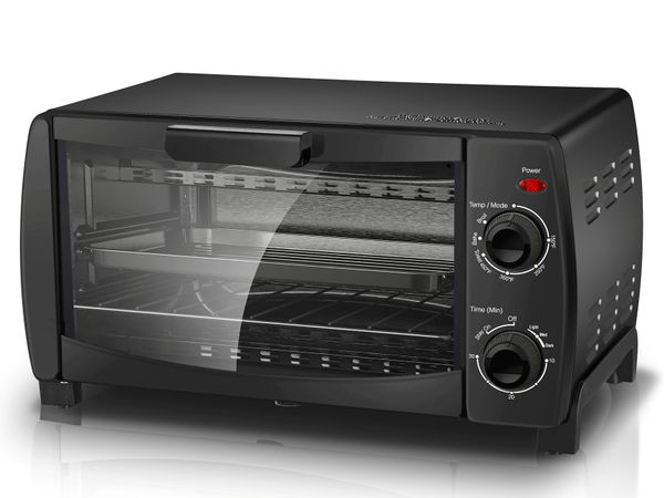
While reading many articles on how to create an effective heating element I found a YouTube video from a guy who was simply using a toaster oven to heat the plastic in an aluminum frame. So, I bought a toaster oven at Wallmart for $19 and gave this method a try. I found that these heating elements provided more than enough heat for this purpose so I incorporated the heat elements and the complete oven control system in my design.
|
| WallMart toaster oven |
Base Build
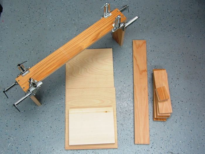
I started with the wood box. Using the 10" Chop saw I could make the corners nearly perfectly square which is a big plus.
|
| Cut wood pieces and box build |
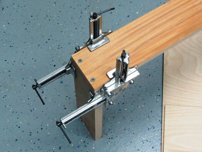
I had a set of picture frame corner clamps which make the set-up and alignment of the corners super easy and solid.
|
| Corner clamps |
After the four corners were complete, I set everything else up and glued them all in with clamps to hold it all in place.
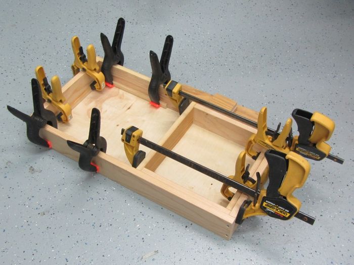
|
| Box build |
With the box completed I then needed to put the two top pieces together and drill the vacuum deck.
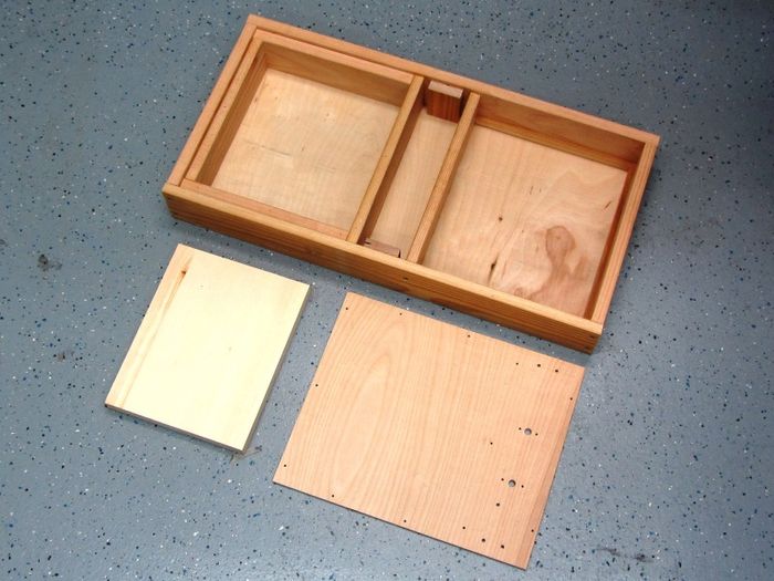
|
| Box and top parts |
I laid out the hole pattern on my computer and printed a template that I used to center-mark the holes.
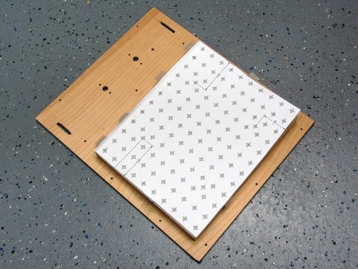
|
| Template for marking and drilling the vac holes |
Frame Build
The two frames are pretty basic builds. Using the chop saw with the 60 tooth carbide blade I first cut to length the for main frame pieces then cut the four mitered pieces for the clamp frame.
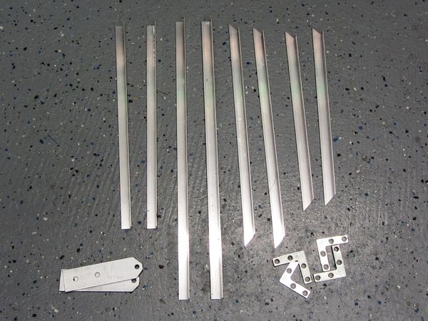
|
| Aluminum frame components |
The clamp frame then required four holes at each corner with the flat side or the aluminum angle being counter sunk to fit the #6-32 x 3/8 screws.
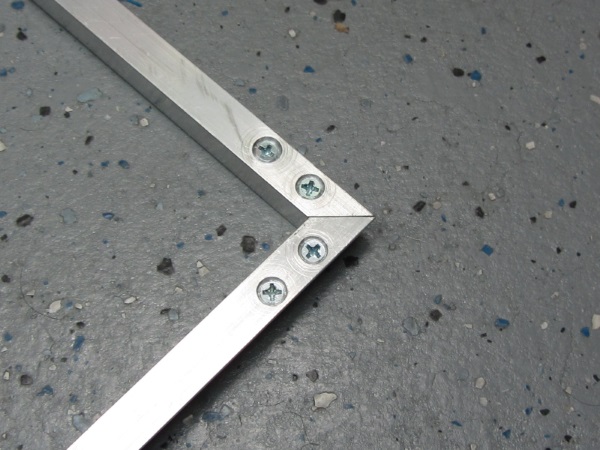
|
| Clamp frame corner detail |
The main frame was put together using corner brackets made from the flat corner brackets I had on hand. These have three holes in each bracket and I used #6-32 flat head screws on the inside flat surface. The two outside screws are #6-32 x 3/8 pan head screws.
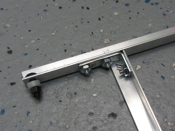
|
| Main frame joint detail |
I then cut a section of the 1/2" dowel stock for the handle and mounted it with a wood screw on each end.
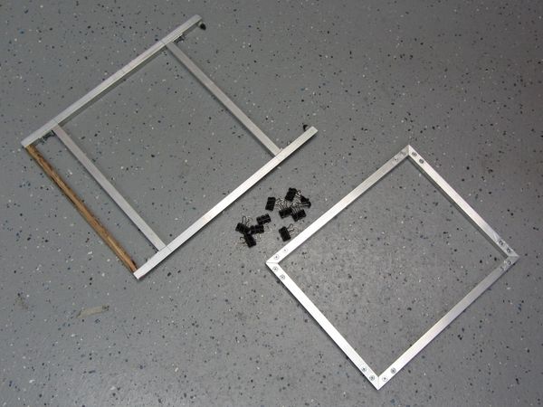
|
| Completed frames |
The completed frames held together with the 10 binder clips.
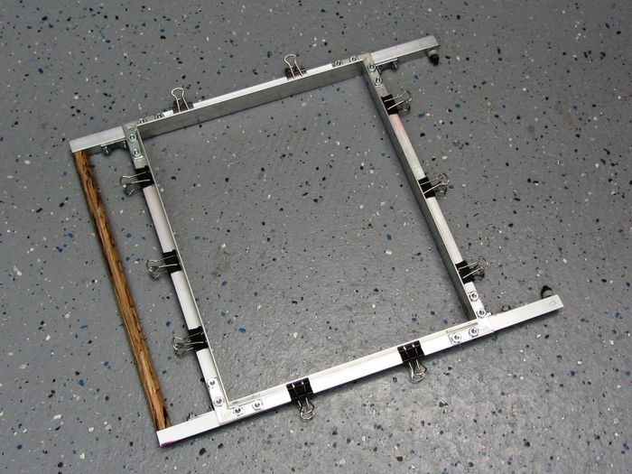
|
| Completed and mounted frames |
Heat Box Build
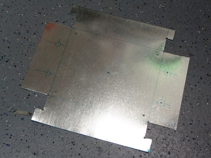
The heater box is made from thin galvanized sheet metal that I found in the air duct section of my local hardware store (Lowes). I layed it out and cut it with small metal shears after drilling all the corner and mount holes.
|
| Sheetmetal layout and cut |
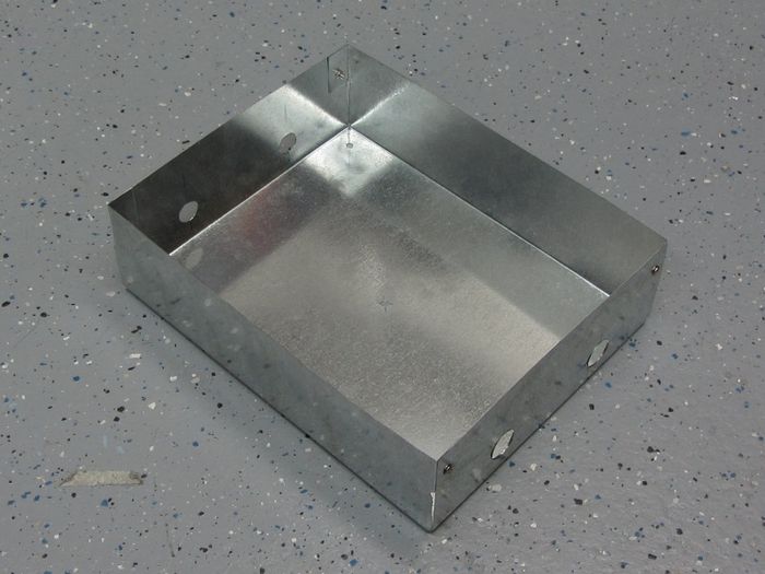
I bent it using a couple of boards and the floor. This sheet metal is thin enough to bend by hand and finish by taping with a wood piece.
|
| Completed heat box |
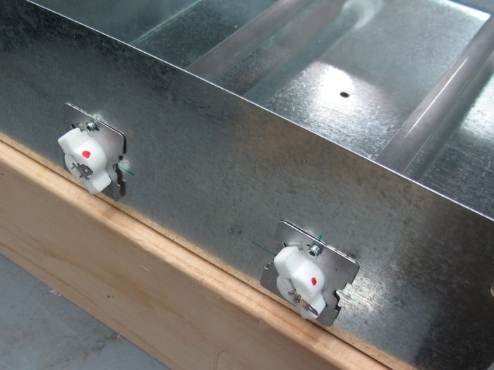
After the box was bent and screwed together, I opened up the four holes and mounted the heater elements. I used the mount plates from the Toaster oven.
|
| Heat element mount detail |
First Vacu-Form!
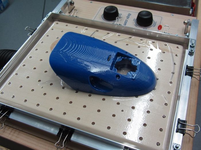
So, for a first try I used a spare 3D printed canopy for one of my Mini Talons. This part is large, has a complex surface with bumps, holes, air vents and some writing on the vertical surfaces.
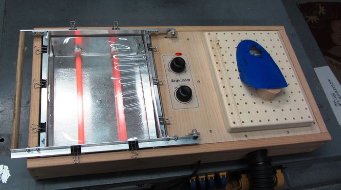
To start I mount a piece of .020 PETG sheet between the frames place the mold piece on the vacuum deck. I then turn on the shop vac and then the heater and wait for the plastic sheet to sag about an inch in the center.
|
| Wait for it! |
Once the plastic has sagged enough, I flip the frame over the mold. The plastic sheet immediately forms over the mold and I shut off the heater and vacuum.
|
| What's that sucking sound? |
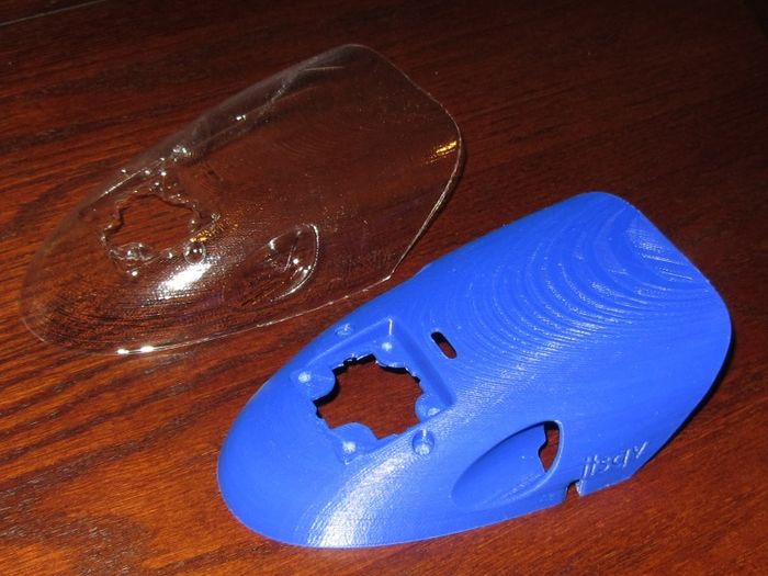
The results of this first piece are excellent! Once parted and cleaned up, it is a perfect match.
|
| A very light, near perfect replacement part! |
Mods
22 June, 2018
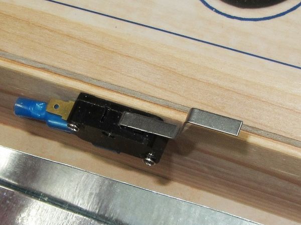
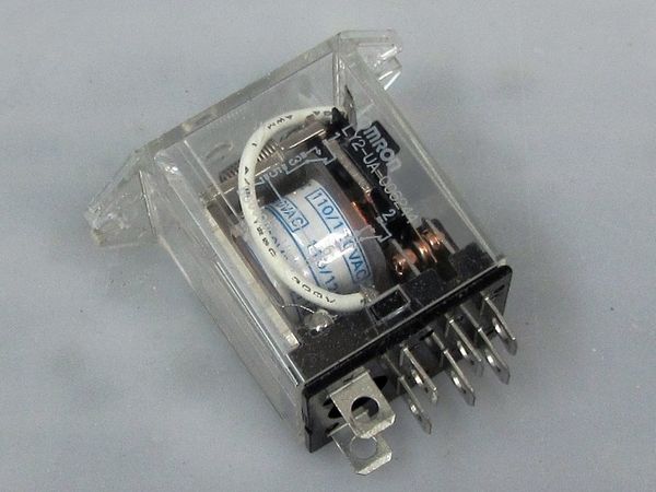
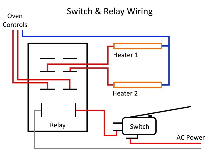
I added a limit switch that controls when the heaters are on. This is coupled to a small relay to handle the higher current of the heaters. The switch functons to only allow the heaters to heat when the frame is down over the heaters and to turn the heaters off when the frame and plastic are flipped over to the vacuum side.
The switch is an SPDT micro switch with a straight lever I could bend to reach the frame -
|
The relay is a DPDT unit with 30A contacts and a 120v coil -
|
|
Switch Parts:
Next!
Next up I will look into creating plaster molds of some of the skids and wing protection parts I have made with other methods.
See Also