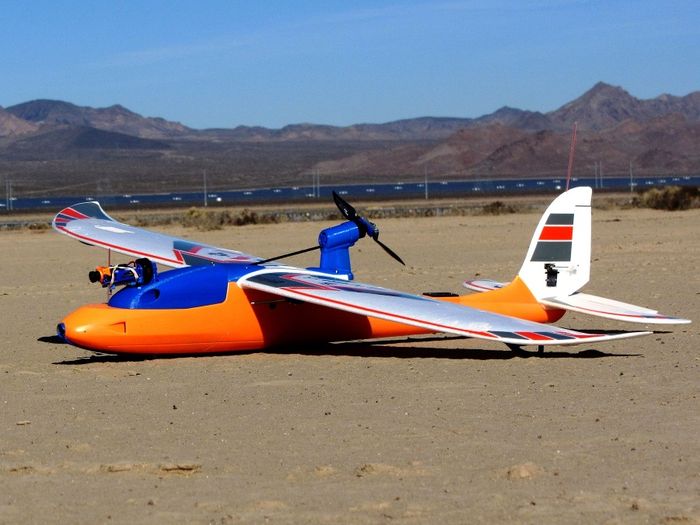
Difference between revisions of "Strix StratoSurfer"
(→General Specifications) |
(→See Also) |
||
| (109 intermediate revisions by the same user not shown) | |||
| Line 1: | Line 1: | ||
[[File:BTI.png|link=AIRCRAFT|AIRCRAFT]]<br> | [[File:BTI.png|link=AIRCRAFT|AIRCRAFT]]<br> | ||
| − | <i><small> | + | [[File:cc_image.png|20px]]<i><small> Mark Qvale - January, 2018</small></i><br> |
{| cellspacing="1" cellpadding="1" width="95%" border="0" | {| cellspacing="1" cellpadding="1" width="95%" border="0" | ||
|- | |- | ||
| align="left" valign="bottom" width="30%" | __TOC__ | | align="left" valign="bottom" width="30%" | __TOC__ | ||
| − | | align="right" width="70%" | [[File: | + | | align="right" valign="top" width="70%" | [[File:SS005c.JPG|700px]] |
| − | + | ||
| − | + | ||
| − | + | ||
|} | |} | ||
| + | <br> | ||
==<br> Introduction == | ==<br> Introduction == | ||
| Line 18: | Line 16: | ||
== General Specifications == | == General Specifications == | ||
| − | Distributor - [http://www. | + | Distributor - '''[http://www.readymaderc.com/ ReadyMadeRC, USA]'''<br>Aircraft - Strix Stratosurfer<br>Build Date - January, 2018<br> |
Update - 5 February, 2018<br><br> | Update - 5 February, 2018<br><br> | ||
| − | {| border="0" cellspacing="1" cellpadding="1" width= | + | {| border="0" cellspacing="1" cellpadding="1" width=95% align="center" |
|- | |- | ||
| align="right" | Airframe Type - | | align="right" | Airframe Type - | ||
| Line 27: | Line 25: | ||
| width="75" | | | width="75" | | ||
| align="right" | All-Up Weight - | | align="right" | All-Up Weight - | ||
| − | | | + | | 59oz (1670g) w/ 4S/7000 Li-ion Pack |
|- | |- | ||
| align="right" | Wingspan - | | align="right" | Wingspan - | ||
| Line 33: | Line 31: | ||
| | | | ||
| align="right" | | | align="right" | | ||
| − | | 56oz ( | + | | 56oz (1676g) w/ 4S/5200 Li-Poly Pack |
|- | |- | ||
| align="right" | Length - | | align="right" | Length - | ||
| Line 45: | Line 43: | ||
| | | | ||
| align="right" | Wing Load w/5200mAh/4S - | | align="right" | Wing Load w/5200mAh/4S - | ||
| − | | | + | | 19.7 oz/ft^2 (61g/dm^2) |
|- | |- | ||
| align="right" | Motor - | | align="right" | Motor - | ||
| − | | | + | | Cobra C2217/16-1180kv |
| | | | ||
| align="right" | Max Continuous Power (4S) - | | align="right" | Max Continuous Power (4S) - | ||
| − | | | + | | 360 watts (4S) |
|- | |- | ||
| align="right" | Propeller - | | align="right" | Propeller - | ||
| − | | | + | | 8x7 Aeronaut Cam Carbon Folder |
| | | | ||
| align="right" | Max Prop Power - | | align="right" | Max Prop Power - | ||
| − | | | + | | 358 watts @ 2550ft ASL |
|- | |- | ||
| − | | align="right" | Static Thrust - | + | | align="right" | Static Thrust & Prop Speed - |
| − | | | + | | 1245g & 88mph @ 2550ft ASL |
| | | | ||
| align="right" | Static Thrust/Weight - | | align="right" | Static Thrust/Weight - | ||
| − | | 0. | + | | 0.75 |
|- | |- | ||
| align="right" | Battery Type - | | align="right" | Battery Type - | ||
| Line 72: | Line 70: | ||
|- | |- | ||
| align="right" | In flight efficiency - | | align="right" | In flight efficiency - | ||
| − | | | + | | <135mAh/mile (<84mAh/km) Typ. |
| | | | ||
| align="right" | Flight Time - | | align="right" | Flight Time - | ||
| − | | | + | | 80 min |
|- | |- | ||
| align="right" | | | align="right" | | ||
| Line 97: | Line 95: | ||
==== Power Set-up ==== | ==== Power Set-up ==== | ||
| − | For power on this build I | + | For power on this build I plan to use a Cobra 2217/16-1180kv motor and a Hobbywing 40A v5 ESC with its active freewheeling and awesome 8A, super quiet BEC. Initially I started with the Sunnysky X2216-1250kv and a HobbyKing Blue Series 40A with a pair of Low ESR capacitors added.<br> |
| − | :* Motor - | + | :* Motor - Cobra 2217/16-1180kv |
| − | :* ESC - | + | :* ESC - Hobbywing Flyfun 40A-'''V5''' |
:* Prop - Aeronaut Cam Carbon Folder, 8x7 | :* Prop - Aeronaut Cam Carbon Folder, 8x7 | ||
:: For more informaion on setting up a pusher folding prop - <u>[[How_To_-_Set-Up_a_Pusher_Style_Folding_Prop | How To - Set-Up a Pusher Style Folding Prop]]</u> | :: For more informaion on setting up a pusher folding prop - <u>[[How_To_-_Set-Up_a_Pusher_Style_Folding_Prop | How To - Set-Up a Pusher Style Folding Prop]]</u> | ||
| Line 107: | Line 105: | ||
{| border="0" cellspacing="1" cellpadding="1" width="800" align="center" | {| border="0" cellspacing="1" cellpadding="1" width="800" align="center" | ||
|- | |- | ||
| − | | align="center" | [[File: | + | | align="center" | [[File:SS87.JPG|700px]] |
|- | |- | ||
| − | | align="center" | | + | | align="center" | Prop chart for the Cobra motor set-up |
|} | |} | ||
| + | <br><br> | ||
| + | |||
| + | ===== Motor Mount ===== | ||
| + | |||
| + | While I did start with a 3D printed offset motor mount (shown below), I no longer think this is a viable approach for this particular plane. Off-setting the motor weight puts a huge amount of stress on the foam that supports it when landing. In my case, using an offset mount on the stock foam setup has resulted in two failures of the foam motor/wing mount assembly. | ||
| + | <br><br> | ||
| + | For more information please see "<u>[[Strix StratoSurfer Motor Mount Design Study]]</u>" | ||
<br> | <br> | ||
| − | {| border="0" cellspacing="1" cellpadding="1" width=" | + | {| border="0" cellspacing="1" cellpadding="1" width="800" align="center" |
|- | |- | ||
| − | | align="center" | [[File: | + | | align="center" | [[File:SS28.jpg|600px]] |
| + | |- | ||
| + | | align="center" | Offset mount | ||
|} | |} | ||
| − | <br> | + | <br><br> |
| + | <!-- | ||
| + | '''More Information'''<br> | ||
| − | + | The stock mount has very little foam in cross section to support the plastic mount pieces and the motor so any additional weight or leverage will put this foam piece under enormous stress. Even with a stock motor set-up this mount could eventually fail after a few hard-stop landings. Below is a general sketch and some photos of an un-assembled stock foam mount and you can see where the weakness is. <br> | |
| − | + | {| border="0" cellspacing="1" cellpadding="1" width="800" align="center" | |
| + | |- | ||
| + | | align="center" | [[File:SS121.jpg|800px]] | ||
| + | |} | ||
| + | <br> | ||
| − | {| border="0" cellspacing="1" cellpadding="1" width=" | + | {| border="0" cellspacing="1" cellpadding="1" width="800" align="center" |
| − | + | ||
| − | + | ||
|- | |- | ||
| − | | align="center" | | + | | align="center" | [[File:SMB7.jpg|700px]] |
|} | |} | ||
<br> | <br> | ||
| − | {| border="0" cellspacing="1" cellpadding="1" width=" | + | {| border="0" cellspacing="1" cellpadding="1" width="800" align="center" |
|- | |- | ||
| − | | align="center" | [[File: | + | | align="center" | [[File:SMB5.jpg|700px]] |
| + | |} | ||
| + | <br> | ||
| + | {| border="0" cellspacing="1" cellpadding="1" width="800" align="center" | ||
|- | |- | ||
| − | | align="center" | | + | | align="center" | [[File:SMB6.jpg|700px]] |
|} | |} | ||
<br> | <br> | ||
| − | {| border="0" cellspacing="1" cellpadding="1" width=" | + | Below is a picture of a failed mount showing how small the area of foam support is. The area highlighted in yellow is all that supports the motor and the motors center of mass is above the weakest part of this support putting it in an extreme stress condition anytime the plane comes to a fast stop.<br><br> |
| − | + | ||
| − | + | {| border="0" cellspacing="1" cellpadding="1" width="800" align="center" | |
|- | |- | ||
| − | | align="center" | | + | | align="center" | [[File:SS123.jpg|700px]] |
|} | |} | ||
<br><br> | <br><br> | ||
| + | |||
| + | If there was some kind of structural tie-in to the wing mount bolts it would be considerably stronger. Below is an illustration of just one idea for a stronger part to be embedded into the foam. <br> | ||
| + | |||
| + | {| border="0" cellspacing="1" cellpadding="1" width="800" align="center" | ||
| + | |- | ||
| + | | align="center" | [[File:SS125.jpg|700px]] | ||
| + | |}<br><br> | ||
| + | --> | ||
| + | |||
| + | === Strengthen it! === | ||
| + | |||
| + | If you are going to use stock size motor and prop it is still a good idea to strengthen this piece. Below is a 3D print that can be inserted and glued to an existing mount. It is 5mm thick and will more effectively support the stock mount by connecting it to the wood ESC plate.<br> | ||
| + | |||
| + | {| border="0" cellspacing="1" cellpadding="1" width="800" align="center" | ||
| + | |- | ||
| + | | align="center" | [[File:SMB1.jpg|700px]] | ||
| + | |}<br> | ||
| + | |||
| + | {| border="0" cellspacing="1" cellpadding="1" width="800" align="center" | ||
| + | |- | ||
| + | | align="center" | [[File:SMB2.jpg|800px]] | ||
| + | |}<br> | ||
| + | |||
| + | Here is an STL print file for the above part - [http://www.itsqv.com/share/Stratosurfer_Motor_Mount_Brace_v4r1.zip Mount Brace-small] | ||
| + | <br><br> | ||
| + | |||
| + | If you are replacing a broken mount, you can use the piece below which is similar to the one above but adds a glued connection to the stock screw insert piece.<br> | ||
| + | |||
| + | {| border="0" cellspacing="1" cellpadding="1" width="800" align="center" | ||
| + | |- | ||
| + | | align="center" | [[File:SMB3.jpg|700px]] | ||
| + | |}<br> | ||
| + | |||
| + | {| border="0" cellspacing="1" cellpadding="1" width="800" align="center" | ||
| + | |- | ||
| + | | align="center" | [[File:SMB4.jpg|800px]] | ||
| + | |}<br> | ||
| + | |||
| + | Here is an STL print file for the above part - [http://www.itsqv.com/share/Stratosurfer_Motor_Mount_Brace_v3r3.zip Mount Brace-large] | ||
| + | <br><br> | ||
| + | |||
| + | Another good fix would be to add a compression piece between the front screw insert and the back of the mount as poster U2builder showed on RCGroups. | ||
| + | |||
| + | {| border="0" cellspacing="1" cellpadding="1" width="800" align="center" | ||
| + | |- | ||
| + | | align="center" | [[File:SMB8.jpg|800px]] | ||
| + | |}<br><br> | ||
| + | |||
| + | For my plane, I have designed a 3D printed motor pod and wing mount that is taller and all tied together into the wing mount bolts. You can see more of this below.<br><br> | ||
''' ESC Mount '''<br> | ''' ESC Mount '''<br> | ||
| Line 161: | Line 224: | ||
==== Flight Control ==== | ==== Flight Control ==== | ||
| − | For flight control I | + | For initial flight control I chose the Omnibus F3Pro from Banggood. It is an inexpensive and in my experience completely reliable FC running iNav 1.8. I flew this FC for 22 flights.<br><br> |
| + | For a second, more programmable flight controller, I changed to an APM Mini 3.1 using Ardupilot 3.4 firmware. I have a lot of APM experience and it showed in the first few flights which were much more stable and controlled than with the F3Pro board. I flew this FC for another 18 flights.<br><br> | ||
| + | |||
| + | The third flight controller is an Eagle Tree Vector I have had on the shelf for some time. What's not to like about the vector? In two flights I had it dialed in and flying near perfectly.<br><br> | ||
| + | |||
| + | The fourth, and definitely last (November 2018), controller is the Matek F405-wing running Chibios/Arduplane firmware. This controller, priced under $50 is by far the best all around board I have found. It has every feature you will find in a Pixhawk, no need for extra BEC's/Voltage regulators, on-board current sense and an excellent OSD. | ||
| + | |||
| + | Here are links to these boards -<br> | ||
:* [https://www.banggood.com/30-5-30-5mm-Betaflight-Omnibus-STM32F3-F3-Pro-Flight-Controller-Built-in-OSD-BEC-Current-sensor-for-RC-Drone-p-1156615.html?rmmds=search&cur_warehouse=CN Omnibus F3Pro] | :* [https://www.banggood.com/30-5-30-5mm-Betaflight-Omnibus-STM32F3-F3-Pro-Flight-Controller-Built-in-OSD-BEC-Current-sensor-for-RC-Drone-p-1156615.html?rmmds=search&cur_warehouse=CN Omnibus F3Pro] | ||
| − | :: | + | :* [http://www.readytoflyquads.com/minireadytoflyer-2-6-v3-1 APM Mini 3.1] |
| − | + | :* [https://www.readymaderc.com/products/details/eagle-tree-vector-fpv-controller-package-wire-leads Eagle Tree Vector] | |
| − | + | :* [https://www.readymaderc.com/products/details/matek-flight-controller-f405-wing Matek F405-wing] | |
| − | + | ||
| − | + | ||
| − | + | ||
| − | + | ||
| − | + | ||
| − | + | ||
<br> | <br> | ||
''' FC Mount '''<br> | ''' FC Mount '''<br> | ||
| − | To mount the FC I drilled out the existing mount holes to 2.3mm then tapped them to M3 and flooded the tapped holes with thin CA. This makes them more than strong enough for a set of rubber M3x6mm stand-offs.<br> | + | To mount the FC I drilled out the existing mount holes to 2.3mm then tapped them to M3 and flooded the tapped holes with thin CA. This makes them more than strong enough for a set of rubber M3x6mm stand-offs. This mount worked for the APM Mini as well.<br> |
{| border="0" cellspacing="1" cellpadding="1" width="700" align="center" | {| border="0" cellspacing="1" cellpadding="1" width="700" align="center" | ||
|- | |- | ||
| − | | align="center" | [[File: | + | | align="center" | [[File:SS35.jpg|700px]] |
|- | |- | ||
| − | | align="center" | | + | | align="center" | F3Pro - all wired up |
|} | |} | ||
<br><br> | <br><br> | ||
| Line 189: | Line 253: | ||
'''RC Control'''<br> | '''RC Control'''<br> | ||
| − | For radio gear I am using my standard DragonLink V2 system. I have mounted the DL dipole inside the | + | For radio gear I am using my standard DragonLink V2 system. I have mounted the DL dipole inside the vertical stabilizer. The RX is mounted on a printed deck below the GPS mount.The printed part is glued in with contact cement but you could also use E6000 or UHU-POR.<br> |
{| border="0" cellspacing="1" cellpadding="1" width="700" align="center" | {| border="0" cellspacing="1" cellpadding="1" width="700" align="center" | ||
| Line 277: | Line 341: | ||
== Kit/Build Review == | == Kit/Build Review == | ||
| − | I opted for the bare bones kit because I live and fly at 2500ft or more altitude and it has been my experience that most PNP setups are underpowered and supplied with | + | I opted for the bare bones kit because I live and fly at 2500ft or more altitude and it has been my experience that most PNP setups are underpowered and supplied with servos that could be improved, etc. With that said, all in all this is a really nice kit. The linkage components in mine are well made and sized perfectly. There are good, solid stiffeners in the control surfaces and having the channels pre-cut in the wings for servo wires is a big plus.<br><br> |
| − | The plastic fuselage is also a treat. Using plastic makes for an enormous amount of room, it is very stiff and has a nice battery tray pre-installed.<br><br> | + | The plastic fuselage is also a big treat. Using plastic makes for an enormous amount of room, it is very stiff and has a nice battery tray pre-installed.<br><br> |
| − | Here are some points for improvement | + | Here are some of my personal points for improvement:<br> |
| − | :* | + | :* Put some solid structure to tie the motor mount and wing mount screws together and make the motor mount taller to accommodate 8" props!! |
| − | + | ||
:* The screw holding the tail together should be much closer to the bottom of the fuse so you can get it out. A socket head cap screw would help as well. | :* The screw holding the tail together should be much closer to the bottom of the fuse so you can get it out. A socket head cap screw would help as well. | ||
| − | :* The four screws holding the wing and motor pod in place are difficult to get in and out which makes it difficult to break | + | :* The four screws holding the wing and motor pod in place are difficult to get in and out which makes it difficult to break the plane down for travel. Changing them to socket head cap screws would be a big improvement. |
:* Change the main wing spar to a more common CF round tube that slips into a tube in each wing panel. This would make it much easier to take the wings apart. I simply can't get mine apart without damaging them. | :* Change the main wing spar to a more common CF round tube that slips into a tube in each wing panel. This would make it much easier to take the wings apart. I simply can't get mine apart without damaging them. | ||
:* Put some stabilization inside the fuse on each side of the wooden FC mount. This piece is well glued but it still moves around too much. I inserted two pieces of foam down each side to dampen the movement. | :* Put some stabilization inside the fuse on each side of the wooden FC mount. This piece is well glued but it still moves around too much. I inserted two pieces of foam down each side to dampen the movement. | ||
| Line 295: | Line 358: | ||
Maiden - 01 January, 2018<br><br> | Maiden - 01 January, 2018<br><br> | ||
| − | The maiden was uneventful in terms of drama (well, except on the launch!) which is always a good thing. The weather was perfect with temp at ~70F a very light breeze and clear skies. From a flying standpoint, the | + | The maiden was uneventful in terms of drama (well, except on the launch!) which is always a good thing. The weather was perfect with temp at ~70F a very light breeze and clear skies. From a flying standpoint, the Stratosurfer flies very well, very controllable, nice yaw response and can be landed slow enough (for me!) without the use of flaps which I haven't installed. The prop I selected, an Aeronaut 7x6 folder was a bit weak as far as climb-out and launch and I will be changing this to an 8x6 Graupner folder for the next flights. The iNav FC needs some tuning and board alignment adjustment but it did its job and kept the plane stable when asked.<br><br> |
| − | + | ||
| − | + | ||
| − | + | ||
| − | + | ||
| − | + | ||
| − | + | ||
| − | + | ||
| − | <br> | + | |
<plainhtml> | <plainhtml> | ||
| Line 311: | Line 366: | ||
</td></tr></table> | </td></tr></table> | ||
</plainhtml> | </plainhtml> | ||
| + | <br> | ||
| − | + | {| border="0" cellspacing="1" cellpadding="1" align="center" | |
| + | |- | ||
| + | | align="center" | [[File:SS003.jpg|900px]] | ||
| + | |- | ||
| + | | align="center" | Post maiden! | ||
| + | |} | ||
<br><br> | <br><br> | ||
| Line 321: | Line 382: | ||
'''Offset Motor Mount'''<br> | '''Offset Motor Mount'''<br> | ||
| − | I | + | I removed the motor mount plate as the stock mount foam is very weak. Please see the power section above. Parts list below is updated. |
<br><br> | <br><br> | ||
''' RX Mount '''<br> | ''' RX Mount '''<br> | ||
| − | I added two 2.55mm holes with bosses to the bottom of the mount so you can use nylon screws to hold it down. I originally had it glued down with contact cement which came loose. <br><br> | + | I added two 2.55mm holes with bosses to the bottom of the mount which you can tap to M3 so you can use nylon screws to hold it down. I originally had it glued down with contact cement which came loose. <br><br> |
=== Changes & New Parts === | === Changes & New Parts === | ||
| Line 332: | Line 393: | ||
=== APM Mini 3.1 Flight Controller === | === APM Mini 3.1 Flight Controller === | ||
| − | + | After ~22 flights I finally got tired of trying to get the Banggood Omnibus F3 Pro flight controller to perform like an APM. So, I have now replaced it with an APM Mini 3.1 I had "on the shelf" which is basically an APM 2.8 in a small package. It fly's excellent although I will need to add a airspeed sensor to get all the benefits from the APM.<br><br> | |
| + | |||
| + | === And now with Cobra Power and an Eagle Tree vector! === | ||
| + | |||
| + | As stated in the power section above, I have upgraded the motor to a Cobra 2217-1180kv to get a little more efficiency and open the door to possibly use an 8x8 folder. | ||
| + | |||
| + | {| border="0" cellspacing="1" cellpadding="1" width="800" align="center" | ||
| + | |- | ||
| + | | align="center" | [[File:SS81.jpg|600px]] | ||
| + | |- | ||
| + | | align="center" | Cobra power! | ||
| + | |} | ||
| + | <br><br> | ||
| + | |||
| + | 1st it was an iNav board, then an APM Mini 3.1 and now an Eagle Tree Vector I've had "on the shelf" for some time. Below are the various parts mounted. | ||
| + | <br> | ||
| + | |||
| + | {| border="0" cellspacing="1" cellpadding="1" width="800" align="center" | ||
| + | |- | ||
| + | | align="center" | [[File:SS82.jpg|600px]] | ||
| + | |- | ||
| + | | align="center" | Vector mount | ||
| + | |} | ||
| + | <br> | ||
| + | |||
| + | {| border="0" cellspacing="1" cellpadding="1" width="800" align="center" | ||
| + | |- | ||
| + | | align="center" | [[File:SS83.jpg|600px]] | ||
| + | |- | ||
| + | | align="center" | GPS Mount | ||
| + | |} | ||
| + | <br> | ||
| + | |||
| + | {| border="0" cellspacing="1" cellpadding="1" width="800" align="center" | ||
| + | |- | ||
| + | | align="center" | [[File:SS84.jpg|600px]] | ||
| + | |- | ||
| + | | align="center" | Pitot Tube mount - Bottom | ||
| + | |} | ||
| + | <br> | ||
| + | |||
| + | {| border="0" cellspacing="1" cellpadding="1" width="800" align="center" | ||
| + | |- | ||
| + | | align="center" | [[File:SS88.jpg|600px]] | ||
| + | |- | ||
| + | | align="center" | Pitot Tube mount - top | ||
| + | |} | ||
| + | <br><br> | ||
=== Hobbywing Flyfun V5 40A ESC === | === Hobbywing Flyfun V5 40A ESC === | ||
| Line 346: | Line 454: | ||
<br><br> | <br><br> | ||
| − | === 52143 - New FPV Camera Mount === | + | === 52143 & 52144 - New FPV Camera Mount === |
| − | Another mod from my maiden setup is a nose mounted FPV cam. I've seen pictures of others done with a nose cam and I have been on the fence about cutting into it as plastic isn't as easy to patch up as EPO should something go wrong or not work-out. Looking through all my extra gear I found I had a Fatshark 700tvl v2 FPV cam which fits very well inside the nose with only the lens needing a hole in the fuse.<br><br> | + | Another mod from my maiden setup is a nose mounted FPV cam. I've seen pictures of others done with a nose cam and I have been on the fence about cutting into it as plastic isn't as easy to patch up as EPO should something go wrong or not work-out. Looking through all my extra gear I found I had a spare Fatshark 700tvl v2 FPV cam which fits very well inside the nose with only the lens needing a hole in the fuse.<br><br> |
| − | I designed then a 2 piece mount for the | + | I designed then a 2 piece mount for the camera consisting of a camera mount and a lens hood. The lens hood is glued to the cam mount with ABS glue which is incredibly strong (you must print in ABS for this to work!).<br> |
{| border="0" cellspacing="1" cellpadding="1" width="800" align="center" | {| border="0" cellspacing="1" cellpadding="1" width="800" align="center" | ||
|- | |- | ||
| − | | align="center" | [[File:SS109.jpg| | + | | align="center" | [[File:SS109.jpg|600px]] |
|- | |- | ||
| align="center" | Fatshark camera mount assembly | | align="center" | Fatshark camera mount assembly | ||
| Line 362: | Line 470: | ||
{| border="0" cellspacing="1" cellpadding="1" width="800" align="center" | {| border="0" cellspacing="1" cellpadding="1" width="800" align="center" | ||
|- | |- | ||
| − | | align="center" | [[File:SS107.jpg| | + | | align="center" | [[File:SS107.jpg|500px]] |
|- | |- | ||
| align="center" | Shown without lens hood | | align="center" | Shown without lens hood | ||
| Line 370: | Line 478: | ||
{| border="0" cellspacing="1" cellpadding="1" width="800" align="center" | {| border="0" cellspacing="1" cellpadding="1" width="800" align="center" | ||
|- | |- | ||
| − | | align="center" | [[File:SS106.jpg| | + | | align="center" | [[File:SS106.jpg|500px]] |
|} | |} | ||
<br> | <br> | ||
| Line 376: | Line 484: | ||
{| border="0" cellspacing="1" cellpadding="1" width="800" align="center" | {| border="0" cellspacing="1" cellpadding="1" width="800" align="center" | ||
|- | |- | ||
| − | | align="center" | [[File:SS111.jpg| | + | | align="center" | [[File:SS111.jpg|500px]] |
|- | |- | ||
| align="center" | With lens hood glued | | align="center" | With lens hood glued | ||
| Line 382: | Line 490: | ||
<br><br> | <br><br> | ||
| − | Once the two pieces are glued together, a hole is cut in the nose and the assembly is glued in (I am using E6000 glue). The mount is shaped to fit so that the camera and its lens hood are looking down about 2 degrees but some fine tunning is required. It is also a challenge to get it in there as there is not much room for fingers and hands.<br> | + | Once the two pieces are glued together, a hole is cut in the nose and the assembly is glued in (I am using E6000 glue). The mount is shaped to fit so that the camera and its lens hood are looking down about 2 degrees but some fine "Dremel" tunning is required. It is also a challenge to get it in there as there is not much room for fingers and hands.<br> |
{| border="0" cellspacing="1" cellpadding="1" width="800" align="center" | {| border="0" cellspacing="1" cellpadding="1" width="800" align="center" | ||
|- | |- | ||
| − | | align="center" | [[File:SS104.jpg| | + | | align="center" | [[File:SS104.jpg|500px]] |
|- | |- | ||
| align="center" | View from the inside | | align="center" | View from the inside | ||
| Line 394: | Line 502: | ||
{| border="0" cellspacing="1" cellpadding="1" width="800" align="center" | {| border="0" cellspacing="1" cellpadding="1" width="800" align="center" | ||
|- | |- | ||
| − | + | | align="center" | [[File:SS102.jpg|500px]] | |
| − | + | ||
| − | + | ||
| − | + | ||
| − | + | ||
| − | + | ||
| − | | align="center" | [[File:SS102.jpg| | + | |
|- | |- | ||
| − | | align="center" | | + | | align="center" | Bottom view shown with front skid |
|} | |} | ||
<br> | <br> | ||
| Line 408: | Line 510: | ||
{| border="0" cellspacing="1" cellpadding="1" width="800" align="center" | {| border="0" cellspacing="1" cellpadding="1" width="800" align="center" | ||
|- | |- | ||
| − | | align="center" | [[File:SS103.jpg| | + | | align="center" | [[File:SS103.jpg|500px]] |
|} | |} | ||
<br><br> | <br><br> | ||
| − | The last bit is optional. There are two small holes in the mount that can be used for a small | + | The last bit is optional but <i>recommended</i>. There are two small 2.55mm holes in the mount that can be used for a small screw on each side if you want more strength in the mount. You can either tap the holes to M3 and use nylon screws or just use self taping screws. These screws are not shown here but will be added. The camera should lightly press into the mount tightly, if not, put a layer of tape on the sides to tighten it up.<br><br> |
| − | === 52145 - GPS Mount for 36mm | + | === 52145 - GPS Mount for 36mm Square Ublox === |
| − | + | When I changed to an APM flight controller, I decided to try a larger GPS unit with a magnetic compass. This mount then is to fit the new GPS unit.<br> | |
{| border="0" cellspacing="1" cellpadding="1" width="800" align="center" | {| border="0" cellspacing="1" cellpadding="1" width="800" align="center" | ||
|- | |- | ||
| − | | align="center" | [[File: | + | | align="center" | [[File:SS86.JPG|500px]] |
|- | |- | ||
| − | | align="center" | | + | | align="center" | Mount with cover |
|} | |} | ||
<br><br> | <br><br> | ||
| Line 428: | Line 530: | ||
=== 52147 - Prop Strike Protection Plate === | === 52147 - Prop Strike Protection Plate === | ||
| − | Because the plastic fuselage is quite thin and very easily cut, I decided to add a prop strike protection plate. This is also because | + | Because the plastic fuselage is quite thin and very easily cut, I decided to add a prop strike protection plate. This is also because with the offset plate on the stock motor mount, I was worried the foam supporting the motor mount could easily break away from the motor pod and cause prop strikes into the plastic fuselage. |
| + | <br> | ||
| + | The piece shown in the picture is longer, side to side, then the final print version.<br> | ||
{| border="0" cellspacing="1" cellpadding="1" width="800" align="center" | {| border="0" cellspacing="1" cellpadding="1" width="800" align="center" | ||
|- | |- | ||
| − | | align="center" | [[File: | + | | align="center" | [[File:SS85.JPG|500px]] |
|- | |- | ||
| − | | align="center" | Shown with | + | | align="center" | Shown with an APCe 8x6 prop |
|} | |} | ||
<br><br> | <br><br> | ||
| Line 444: | Line 548: | ||
{| border="0" cellspacing="1" cellpadding="1" width="800" align="center" | {| border="0" cellspacing="1" cellpadding="1" width="800" align="center" | ||
|- | |- | ||
| − | | align="center" | [[File: | + | | align="center" | [[File:SS113.JPG|600px]] |
|- | |- | ||
| − | | align="center" | | + | | align="center" | Mounted on the plane, Pan and Tilt version shown |
|} | |} | ||
<br> | <br> | ||
| Line 452: | Line 556: | ||
{| border="0" cellspacing="1" cellpadding="1" width="800" align="center" | {| border="0" cellspacing="1" cellpadding="1" width="800" align="center" | ||
|- | |- | ||
| − | | align="center" | [[File: | + | | align="center" | [[File:SS117.JPG|500px]] |
|- | |- | ||
| − | | align="center" | | + | | align="center" | Plain canopy with mount |
|} | |} | ||
<br> | <br> | ||
| Line 460: | Line 564: | ||
{| border="0" cellspacing="1" cellpadding="1" width="800" align="center" | {| border="0" cellspacing="1" cellpadding="1" width="800" align="center" | ||
|- | |- | ||
| − | | align="center" | [[File: | + | | align="center" | [[File:SS115.JPG|400px]] |
|- | |- | ||
| − | | align="center" | | + | | align="center" | Canopy mount |
|} | |} | ||
<br><br> | <br><br> | ||
| − | === | + | === Full Canopy! === |
| − | Below is a canopy concept I | + | Below is a canopy concept I did some work on for this plane. It is a full length unit that really sets off the planes shape nicely. I did not complete this as it would be very heavy (>60g) and it would be really difficult to print because of its size and the amount of support that would be needed.<br> |
{| border="0" cellspacing="1" cellpadding="1" align="center" | {| border="0" cellspacing="1" cellpadding="1" align="center" | ||
| Line 478: | Line 582: | ||
<br><br> | <br><br> | ||
| − | : | + | === Low Profile Wing and Motor Mount === |
| + | |||
| + | My solution is a two part (5 piece) wing & motor mount that are tied together with a 4mm CF tube. This gives the same wing clamping force as the original two screw inserts but adds an immense amount of strength to the motor mount which is now integral to the wing mounts and their screws. It is also extended to allow 8” props. The total mass of these pieces is 24g more than the foam mount with the motor mount insert. <br><br> | ||
| + | |||
| + | {| border="0" cellspacing="1" cellpadding="1" width="800" align="center" | ||
| + | |- | ||
| + | | align="center" | [[File:SS127.JPG|700px]] | ||
| + | |} | ||
<br><br> | <br><br> | ||
| − | == | + | There are 5 parts to this solution: <br> |
| + | :1. Front wing mount cover | ||
| + | :2. Motor mount | ||
| + | :3. ESC wire cover | ||
| + | :4. Motor shroud (optional) | ||
| + | :5. 4mm x 2mm Carbon Fiber tube | ||
| + | |||
| + | {| border="0" cellspacing="1" cellpadding="1" width="800" align="center" | ||
| + | |- | ||
| + | | align="center" | [[File:SS129.JPG|700px]] | ||
| + | |} | ||
<br> | <br> | ||
| − | |||
| − | + | Now, because this is a low profile solution, the front foam canopy base needs to be carefully cut to match the front wing mount piece. Below is a picture of mine with the foam piece cut to match and a spring latch added to replace the magnet. Shown with a 2216 motor and an 8" Aeronaut folding prop.<br> | |
| − | + | {| border="0" cellspacing="1" cellpadding="1" width="800" align="center" | |
| − | + | |- | |
| − | : | + | | align="center" | [[File:SS131.JPG|900px]] |
| − | + | |} | |
| − | <br> | + | <br><br> |
| − | + | Also available, a longer 1 piece canopy to go with all of this. Sure makes the plane look slippery!<br> | |
| − | {| border=" | + | |
| + | {| border="0" cellspacing="1" cellpadding="1" width="800" align="center" | ||
|- | |- | ||
| − | | | + | | align="center" | [[File:SS134.JPG|900px]] |
| − | | | + | |} |
| − | + | <br><br> | |
| − | | | + | |
| − | + | === Roll Gimbal! === | |
| − | + | ||
| + | Finally got around to printing the low profile canopy with my standard 4 bolt mount to fit my Pan and Tilts and the same Brushless Roll Gimbal I use on my Mini Talon. It does add a fair amount of weight but the video result are awesome and so worth it! <br> | ||
| + | |||
| + | {| border="0" cellspacing="1" cellpadding="1" width="800" align="center" | ||
|- | |- | ||
| − | | align=" | + | | align="center" | [[File:SS161.JPG|900px]] |
| − | + | ||
| − | + | ||
| − | + | ||
| − | + | ||
| − | + | ||
|- | |- | ||
| − | | align=" | + | | align="center" | Mounted with a RunCam Split |
| − | | | + | |} |
| − | + | <br> | |
| − | + | ||
| − | + | For control I am using a Storm32 V1.1 BGC control board which works very well and it has an integrated Bluetooth module for easy connection and tuning. (video below)<br> | |
| − | + | ||
| + | {| border="0" cellspacing="1" cellpadding="1" width="800" align="center" | ||
|- | |- | ||
| − | | align=" | + | | align="center" | [[File:SS163.JPG|800px]] |
| − | + | ||
| − | + | ||
| − | + | ||
| − | + | ||
| − | + | ||
|- | |- | ||
| − | | align=" | + | | align="center" | Mounted with a RunCam Split |
| − | + | ||
| − | + | ||
| − | + | ||
| − | + | ||
| − | + | ||
| − | + | ||
| − | + | ||
| − | + | ||
| − | + | ||
| − | + | ||
| − | + | ||
| − | + | ||
| − | + | ||
| − | + | ||
| − | + | ||
| − | + | ||
| − | + | ||
| − | + | ||
| − | + | ||
| − | + | ||
| − | + | ||
| − | + | ||
| − | + | ||
| − | + | ||
| − | + | ||
| − | + | ||
| − | + | ||
| − | + | ||
| − | + | ||
| − | + | ||
| − | + | ||
| − | + | ||
| − | + | ||
| − | + | ||
| − | + | ||
| − | + | ||
| − | + | ||
| − | + | ||
| − | + | ||
| − | + | ||
|} | |} | ||
| − | |||
| − | |||
<br> | <br> | ||
| − | {| border=" | + | |
| + | ==== Roll Gimbal Video ==== | ||
| + | |||
| + | Here you can see a short demo that has no post processing for stability. There is a very small amount of yaw wobble and a little nose bobing caused by the FC which needs a little tuning. | ||
| + | <br> | ||
| + | |||
| + | <plainhtml> | ||
| + | <table align="center" width="900" border="0"><tr><td align="center"> | ||
| + | <iframe width="853" height="480" src="https://www.youtube.com/embed/3Zj1Y3Kb6Y4" frameborder="0" allow="autoplay; encrypted-media" allowfullscreen></iframe> | ||
| + | <p>Roll Gimbal test - 4 October, 2018</p> | ||
| + | </td></tr></table> | ||
| + | </plainhtml> | ||
| + | <br><br> | ||
| + | |||
| + | === Parting Shot === | ||
| + | |||
| + | {| border="0" cellspacing="1" cellpadding="1" width="800" align="center" | ||
|- | |- | ||
| − | | | + | | align="center" | [[File:SS151.jpg|1000px]] |
| − | + | ||
| − | + | ||
| − | + | ||
| − | + | ||
| − | + | ||
|- | |- | ||
| − | | align=" | + | | align="center" | (That "lake" in the background is actually a solar plant!) |
| − | + | |} | |
| − | | | + | <br><br> |
| − | + | ||
| − | | | + | {| style="border-right: #aaa 1px solid; border-top: #aaa 1px solid; background: #fbfbfb; margin: 0px 0px 0px 10%; border-left: #1e90ff 10px solid; width: 80%; border-bottom: #aaa 1px solid; border-collapse: collapse" |
| − | + | ||
|- | |- | ||
| − | | | + | | style="padding-right: 0px; padding-left: 0.5em; padding-bottom: 2px; width: 52px; padding-top: 2px; text-align: center" | [[File:Tools.jpg|42px]] |
| − | + | | style="padding-right: 0.5em; padding-left: 0.5em; padding-bottom: 0.25em; padding-top: 0.25em" | '''The Strix Stratosurfer has been converted to a Twin Tractor setup and can now be found on a new page!''' | |
| − | + | <small><u>'''[[Strix StratoSurfer Twin Conversion]]</u></small> | |
| − | + | |} | |
| − | + | <br> | |
| − | + | ||
| − | + | ||
| − | + | ||
| − | + | ||
| − | + | ||
| − | + | ||
| − | + | ||
| − | + | ||
| − | + | ||
| − | + | ||
| − | | | + | |
| − | + | ||
| − | + | ||
| − | + | ||
| − | + | ||
| − | + | ||
| − | + | ||
| − | + | ||
| − | + | ||
| − | + | ||
| − | + | ||
| − | + | ||
| − | + | ||
| − | + | ||
| − | + | ||
| − | + | ||
| − | + | ||
| − | + | ||
| − | + | ||
| − | + | ||
| − | + | ||
| − | + | ||
| − | + | ||
| − | + | ||
| − | + | ||
| − | + | ||
| − | + | ||
| − | + | ||
| − | + | ||
| − | + | ||
| − | + | ||
| − | + | ||
| − | | | + | |
| − | + | ||
| − | == | + | == Project 3D Print Files == |
| + | <br> | ||
| + | All parts can be found on the '''<u>[[Parts Catalog - Strix Stratosurfer | Strix Stratosurfer parts catalog]]</u>''' page.<br><br> | ||
| − | :* [[ | + | == See Also == |
| + | <br> | ||
| + | :* [[Strix StratoSurfer Twin Conversion]] | ||
| + | :* [[Parts Catalog - Strix Stratosurfer]] | ||
:* [[Current Parts Catalogs]] | :* [[Current Parts Catalogs]] | ||
:* [https://www.thingiverse.com/markqv/designs Thingiverse Design Page] | :* [https://www.thingiverse.com/markqv/designs Thingiverse Design Page] | ||
| Line 644: | Line 688: | ||
=== Some of the Vendors I used for this project === | === Some of the Vendors I used for this project === | ||
| − | + | <br> | |
: [http://www.readymaderc.com/store/ Ready Made RC] | : [http://www.readymaderc.com/store/ Ready Made RC] | ||
| − | : [ | + | : [https://www.hobbywingdirect.com/products/flyfun-v5-esc-3s-6s?variant=31797909521 HobbyWing North America] |
: [https://alofthobbies.com/ Aloft Hobbies] | : [https://alofthobbies.com/ Aloft Hobbies] | ||
| Line 652: | Line 696: | ||
=== Comments? Questions? === | === Comments? Questions? === | ||
| − | + | <br> | |
:'''<u>[mailto:qmar80@hotmail.com?Subject=About%20The%20Strix%20Strato-Surfer&body=Question? email me!]</u>''' | :'''<u>[mailto:qmar80@hotmail.com?Subject=About%20The%20Strix%20Strato-Surfer&body=Question? email me!]</u>''' | ||
Latest revision as of 12:25, 12 April 2020
Introduction
I decided to try something different and having never gone down the Bixler style road, the Strix StratoSurfer seemed like a good place to start. Also, after reading much about this plane, I decided to start with a larger motor/prop combo. For flight management/control I'll be starting with an Omnibus F3Pro flight controller to keep it light and simple.
Here then is a collection of my build notes and eventually a flight review of this plane.
General Specifications
Distributor - ReadyMadeRC, USA
Aircraft - Strix Stratosurfer
Build Date - January, 2018
Update - 5 February, 2018
| Airframe Type - | Top Wing FPV Specialist | All-Up Weight - | 59oz (1670g) w/ 4S/7000 Li-ion Pack | |
| Wingspan - | 59 inches (1500mm) | 56oz (1676g) w/ 4S/5200 Li-Poly Pack | ||
| Length - | 39 inches (1000mm) | COG - | 65mm - 70mm @ Wing root (Stock) | |
| Wing Area - | 2.95 ft^2 (27.4dm^2) | Wing Load w/5200mAh/4S - | 19.7 oz/ft^2 (61g/dm^2) | |
| Motor - | Cobra C2217/16-1180kv | Max Continuous Power (4S) - | 360 watts (4S) | |
| Propeller - | 8x7 Aeronaut Cam Carbon Folder | Max Prop Power - | 358 watts @ 2550ft ASL | |
| Static Thrust & Prop Speed - | 1245g & 88mph @ 2550ft ASL | Static Thrust/Weight - | 0.75 | |
| Battery Type - | 4S1P Lipo -or- 4S2P Li-ion | Battery Capacity - | 5200mAh/10C or 7000mah/3C | |
| In flight efficiency - | <135mAh/mile (<84mAh/km) Typ. | Flight Time - | 80 min | |
Components/Flight Gear
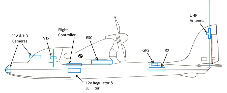
Below is the approximate layout of installed components:
|
Power Set-up
For power on this build I plan to use a Cobra 2217/16-1180kv motor and a Hobbywing 40A v5 ESC with its active freewheeling and awesome 8A, super quiet BEC. Initially I started with the Sunnysky X2216-1250kv and a HobbyKing Blue Series 40A with a pair of Low ESR capacitors added.
- Motor - Cobra 2217/16-1180kv
- ESC - Hobbywing Flyfun 40A-V5
- Prop - Aeronaut Cam Carbon Folder, 8x7
- For more informaion on setting up a pusher folding prop - How To - Set-Up a Pusher Style Folding Prop
- Battery - Multistar 4S/5200, 10C or a 4S/7000 Li-Ion
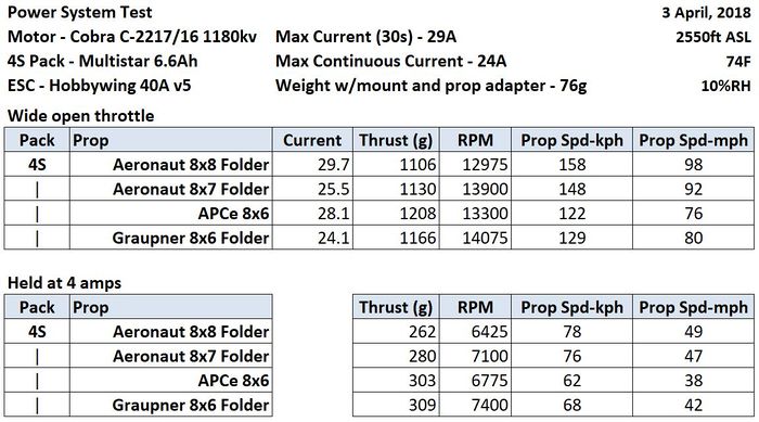
|
| Prop chart for the Cobra motor set-up |
Motor Mount
While I did start with a 3D printed offset motor mount (shown below), I no longer think this is a viable approach for this particular plane. Off-setting the motor weight puts a huge amount of stress on the foam that supports it when landing. In my case, using an offset mount on the stock foam setup has resulted in two failures of the foam motor/wing mount assembly.
For more information please see "Strix StratoSurfer Motor Mount Design Study"
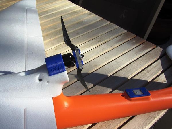
|
| Offset mount |
Strengthen it!
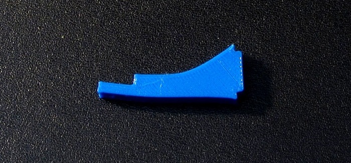
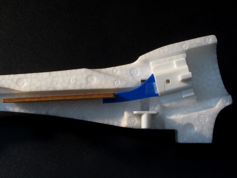
If you are going to use stock size motor and prop it is still a good idea to strengthen this piece. Below is a 3D print that can be inserted and glued to an existing mount. It is 5mm thick and will more effectively support the stock mount by connecting it to the wood ESC plate.
|
|
Here is an STL print file for the above part - Mount Brace-small
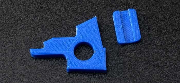
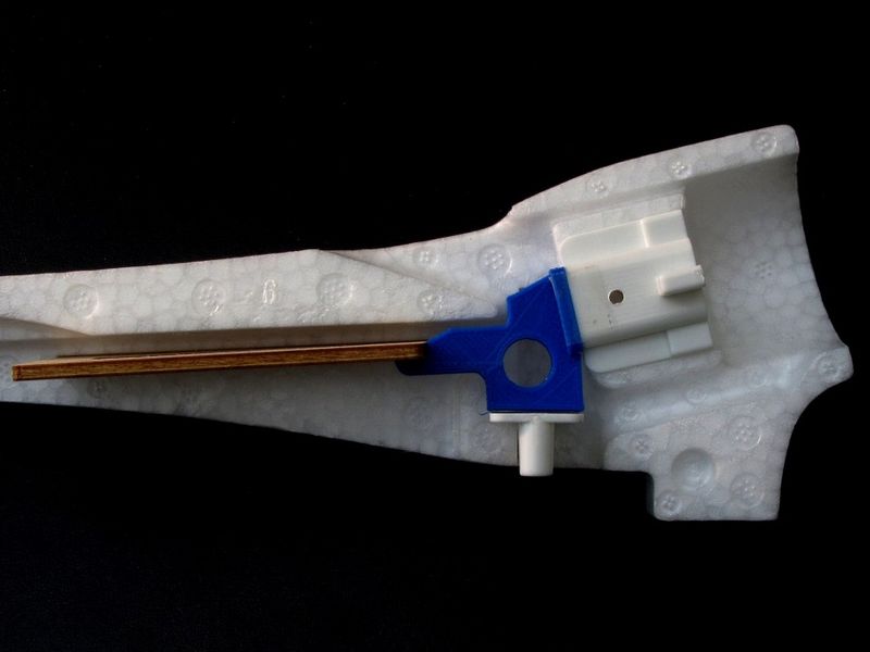
If you are replacing a broken mount, you can use the piece below which is similar to the one above but adds a glued connection to the stock screw insert piece.
|
|
Here is an STL print file for the above part - Mount Brace-large
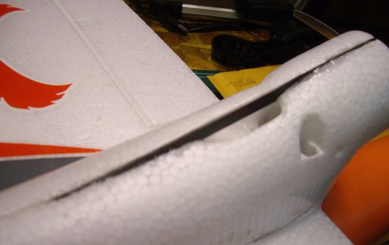
Another good fix would be to add a compression piece between the front screw insert and the back of the mount as poster U2builder showed on RCGroups.
|
For my plane, I have designed a 3D printed motor pod and wing mount that is taller and all tied together into the wing mount bolts. You can see more of this below.
ESC Mount
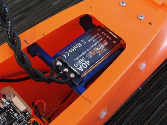
I decided to design and print a simple mount to hold the ESC. It mounts with four M3x6mm nylon screws and a wire tie to hold the ESC. This print is sized for a 25mm wide ESC.
|
| ESC craddle |
Flight Control
For initial flight control I chose the Omnibus F3Pro from Banggood. It is an inexpensive and in my experience completely reliable FC running iNav 1.8. I flew this FC for 22 flights.
For a second, more programmable flight controller, I changed to an APM Mini 3.1 using Ardupilot 3.4 firmware. I have a lot of APM experience and it showed in the first few flights which were much more stable and controlled than with the F3Pro board. I flew this FC for another 18 flights.
The third flight controller is an Eagle Tree Vector I have had on the shelf for some time. What's not to like about the vector? In two flights I had it dialed in and flying near perfectly.
The fourth, and definitely last (November 2018), controller is the Matek F405-wing running Chibios/Arduplane firmware. This controller, priced under $50 is by far the best all around board I have found. It has every feature you will find in a Pixhawk, no need for extra BEC's/Voltage regulators, on-board current sense and an excellent OSD.
Here are links to these boards -
FC Mount
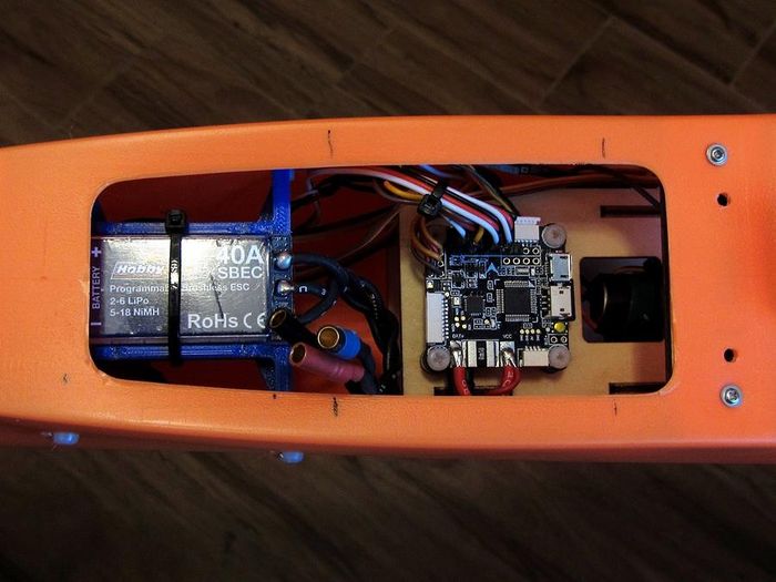
To mount the FC I drilled out the existing mount holes to 2.3mm then tapped them to M3 and flooded the tapped holes with thin CA. This makes them more than strong enough for a set of rubber M3x6mm stand-offs. This mount worked for the APM Mini as well.
|
| F3Pro - all wired up |
RC Control
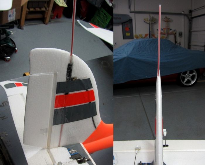
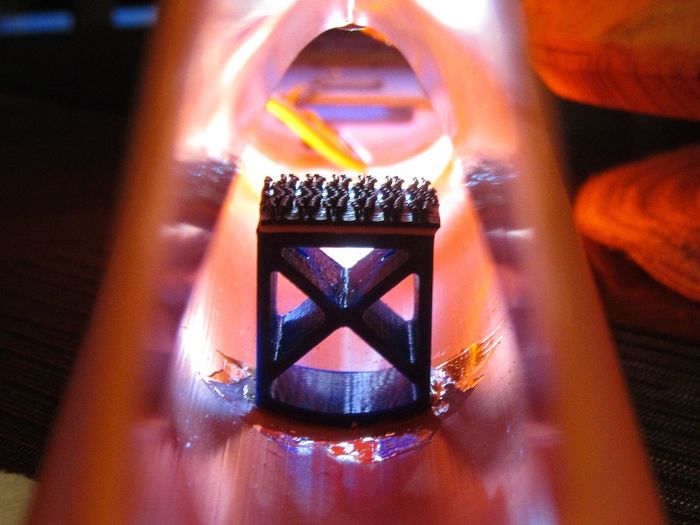
For radio gear I am using my standard DragonLink V2 system. I have mounted the DL dipole inside the vertical stabilizer. The RX is mounted on a printed deck below the GPS mount.The printed part is glued in with contact cement but you could also use E6000 or UHU-POR.
|
| DragonLink UHF antenna |
|
| RX mount |
GPS Mount
For the GPS I created a mount plate to replace the white plate on the rear of the fuse. This is sized for a Ublox Mini M7 GPS.
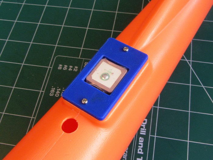
|
FPV Gear
For an initial setup I am using the stock foam cowl piece with simple mounts for the FPV camera, VTx and HD camera. I will be changing to printed canopies as I did on my MiniTalon builds to get a more aerodynamic profile and cool looks! Here are the initial components and a picture of their mounts:
- VTx - RMRC 800mw, 1.3G
- FPV Camera - HS1184 with 2.8 lens
- HD Camera - Mobius Mini
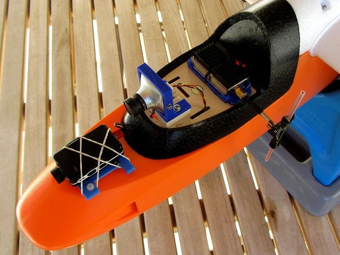
|
| Initial FPV gear |
Airframe
Stabilizers
On the tail linkage I used the stock linkage bits with Hextronic MG14 metal gear digital servos. Of course the standard 1/2" Blenderm tape was added to the hinges for strength.
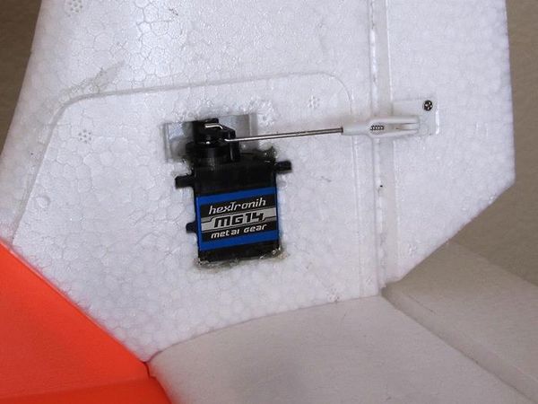
|
Wings
Nothing new or special here. I added 1" (25mm) of 3 mil laminate to the leading edge. Linkage is the same as the elevators and servos are Corona DS929MG's. Blenderm on the hinge line here too.
Fuselage
The beauty of a plastic fuselage is it is already very durable. Because of where I fly (and land) I still felt I needed a little more protection on the nose and rear skid so I designed up a couple of skids which conform to the fuselage shape. The new nose skid also has a provision for a bolt-on tow hook which I will add later. These are printed in ABS at 80% infil for durability. For glue, I used E6000 which is similar to UHU-POR and Beacons FoamTac.
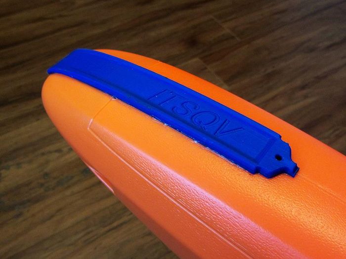
|
| Front skid |
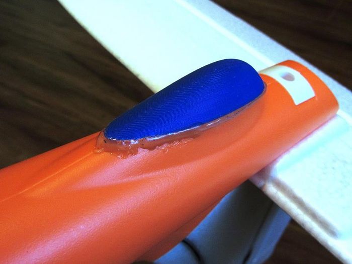
|
| Rear skid (with excessive glue) |
Kit/Build Review
I opted for the bare bones kit because I live and fly at 2500ft or more altitude and it has been my experience that most PNP setups are underpowered and supplied with servos that could be improved, etc. With that said, all in all this is a really nice kit. The linkage components in mine are well made and sized perfectly. There are good, solid stiffeners in the control surfaces and having the channels pre-cut in the wings for servo wires is a big plus.
The plastic fuselage is also a big treat. Using plastic makes for an enormous amount of room, it is very stiff and has a nice battery tray pre-installed.
Here are some of my personal points for improvement:
- Put some solid structure to tie the motor mount and wing mount screws together and make the motor mount taller to accommodate 8" props!!
- The screw holding the tail together should be much closer to the bottom of the fuse so you can get it out. A socket head cap screw would help as well.
- The four screws holding the wing and motor pod in place are difficult to get in and out which makes it difficult to break the plane down for travel. Changing them to socket head cap screws would be a big improvement.
- Change the main wing spar to a more common CF round tube that slips into a tube in each wing panel. This would make it much easier to take the wings apart. I simply can't get mine apart without damaging them.
- Put some stabilization inside the fuse on each side of the wooden FC mount. This piece is well glued but it still moves around too much. I inserted two pieces of foam down each side to dampen the movement.
Maiden!
Maiden - 01 January, 2018
The maiden was uneventful in terms of drama (well, except on the launch!) which is always a good thing. The weather was perfect with temp at ~70F a very light breeze and clear skies. From a flying standpoint, the Stratosurfer flies very well, very controllable, nice yaw response and can be landed slow enough (for me!) without the use of flaps which I haven't installed. The prop I selected, an Aeronaut 7x6 folder was a bit weak as far as climb-out and launch and I will be changing this to an 8x6 Graupner folder for the next flights. The iNav FC needs some tuning and board alignment adjustment but it did its job and kept the plane stable when asked.
|
Maiden Day - 15 January, 2018 |
|
| Post maiden! |
Updates/Mods/Changes
Released Part Updates
Offset Motor Mount
I removed the motor mount plate as the stock mount foam is very weak. Please see the power section above. Parts list below is updated.
RX Mount
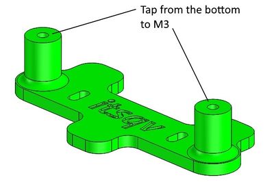
I added two 2.55mm holes with bosses to the bottom of the mount which you can tap to M3 so you can use nylon screws to hold it down. I originally had it glued down with contact cement which came loose.
Changes & New Parts
APM Mini 3.1 Flight Controller
After ~22 flights I finally got tired of trying to get the Banggood Omnibus F3 Pro flight controller to perform like an APM. So, I have now replaced it with an APM Mini 3.1 I had "on the shelf" which is basically an APM 2.8 in a small package. It fly's excellent although I will need to add a airspeed sensor to get all the benefits from the APM.
And now with Cobra Power and an Eagle Tree vector!
As stated in the power section above, I have upgraded the motor to a Cobra 2217-1180kv to get a little more efficiency and open the door to possibly use an 8x8 folder.
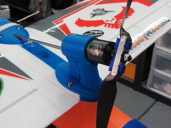
|
| Cobra power! |
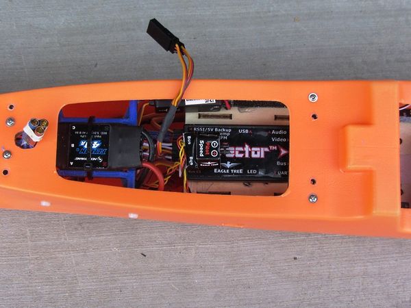
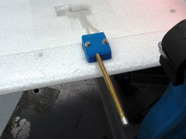
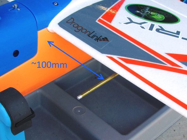
1st it was an iNav board, then an APM Mini 3.1 and now an Eagle Tree Vector I've had "on the shelf" for some time. Below are the various parts mounted.
|
| Vector mount |
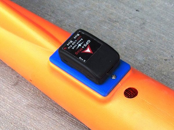
|
| GPS Mount |
|
| Pitot Tube mount - Bottom |
|
| Pitot Tube mount - top |
Hobbywing Flyfun V5 40A ESC
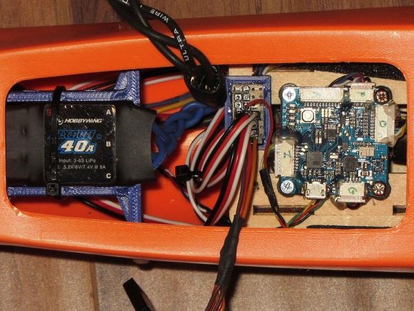
Got another HW Flyfun V5 in and immediately replaced the HK Blue Series 40A. Nothing wrong with the Blue Series but the Flyfun is a much better unit and with their DEO Technology, also known as Active Freewheeling, these units run amazingly cool at any throttle position and are more efficient at power management. Additionally, they come with a 5.2/6.0/7.4 volt BEC that will deliver a full 8 amps/20 amps peak (tested).
|
| New Hobbywing Flyfun v5 and APM Mini 3.1 |
52143 & 52144 - New FPV Camera Mount
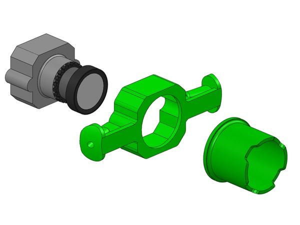
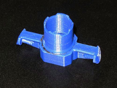
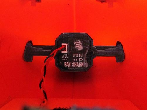
Another mod from my maiden setup is a nose mounted FPV cam. I've seen pictures of others done with a nose cam and I have been on the fence about cutting into it as plastic isn't as easy to patch up as EPO should something go wrong or not work-out. Looking through all my extra gear I found I had a spare Fatshark 700tvl v2 FPV cam which fits very well inside the nose with only the lens needing a hole in the fuse.
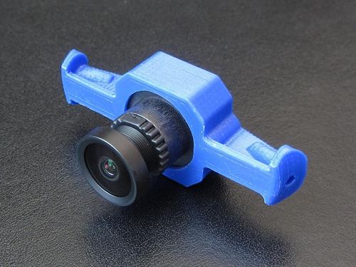
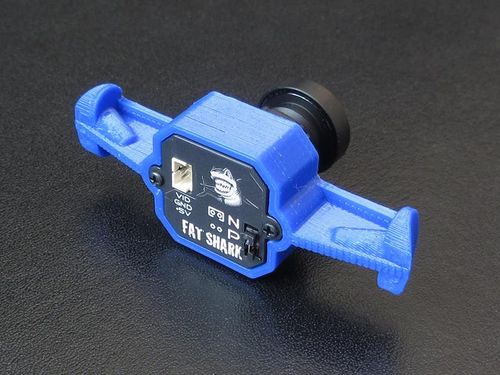
I designed then a 2 piece mount for the camera consisting of a camera mount and a lens hood. The lens hood is glued to the cam mount with ABS glue which is incredibly strong (you must print in ABS for this to work!).
|
| Fatshark camera mount assembly |
|
| Shown without lens hood |
|
|
| With lens hood glued |
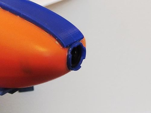
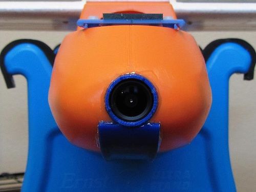
Once the two pieces are glued together, a hole is cut in the nose and the assembly is glued in (I am using E6000 glue). The mount is shaped to fit so that the camera and its lens hood are looking down about 2 degrees but some fine "Dremel" tunning is required. It is also a challenge to get it in there as there is not much room for fingers and hands.
|
| View from the inside |
|
| Bottom view shown with front skid |
|
The last bit is optional but recommended. There are two small 2.55mm holes in the mount that can be used for a small screw on each side if you want more strength in the mount. You can either tap the holes to M3 and use nylon screws or just use self taping screws. These screws are not shown here but will be added. The camera should lightly press into the mount tightly, if not, put a layer of tape on the sides to tighten it up.
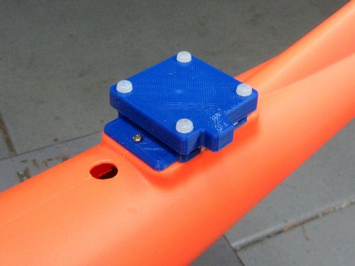
52145 - GPS Mount for 36mm Square Ublox
When I changed to an APM flight controller, I decided to try a larger GPS unit with a magnetic compass. This mount then is to fit the new GPS unit.
|
| Mount with cover |
52147 - Prop Strike Protection Plate
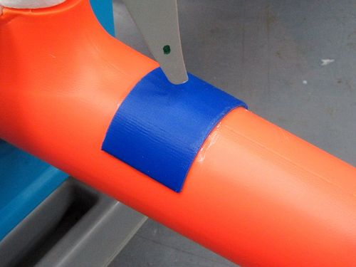
Because the plastic fuselage is quite thin and very easily cut, I decided to add a prop strike protection plate. This is also because with the offset plate on the stock motor mount, I was worried the foam supporting the motor mount could easily break away from the motor pod and cause prop strikes into the plastic fuselage.
The piece shown in the picture is longer, side to side, then the final print version.
|
| Shown with an APCe 8x6 prop |
52148, 52149, 52150 - New Small Canopies
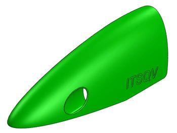
Finally finished the small canopy shape and have released (below) two canopies and a mount that screws down to the plywood deck.
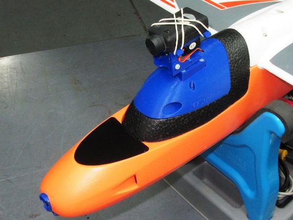
|
| Mounted on the plane, Pan and Tilt version shown |
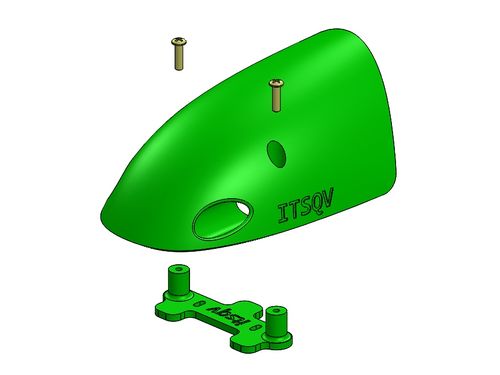
|
| Plain canopy with mount |
|
| Canopy mount |
Full Canopy!
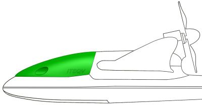
Below is a canopy concept I did some work on for this plane. It is a full length unit that really sets off the planes shape nicely. I did not complete this as it would be very heavy (>60g) and it would be really difficult to print because of its size and the amount of support that would be needed.
|
| Long Canopy concept |
Low Profile Wing and Motor Mount
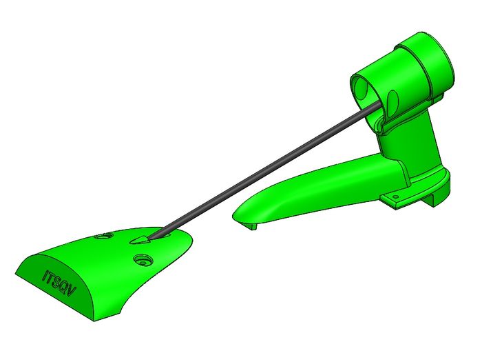
My solution is a two part (5 piece) wing & motor mount that are tied together with a 4mm CF tube. This gives the same wing clamping force as the original two screw inserts but adds an immense amount of strength to the motor mount which is now integral to the wing mounts and their screws. It is also extended to allow 8” props. The total mass of these pieces is 24g more than the foam mount with the motor mount insert.
|
There are 5 parts to this solution:
- 1. Front wing mount cover
- 2. Motor mount
- 3. ESC wire cover
- 4. Motor shroud (optional)
- 5. 4mm x 2mm Carbon Fiber tube
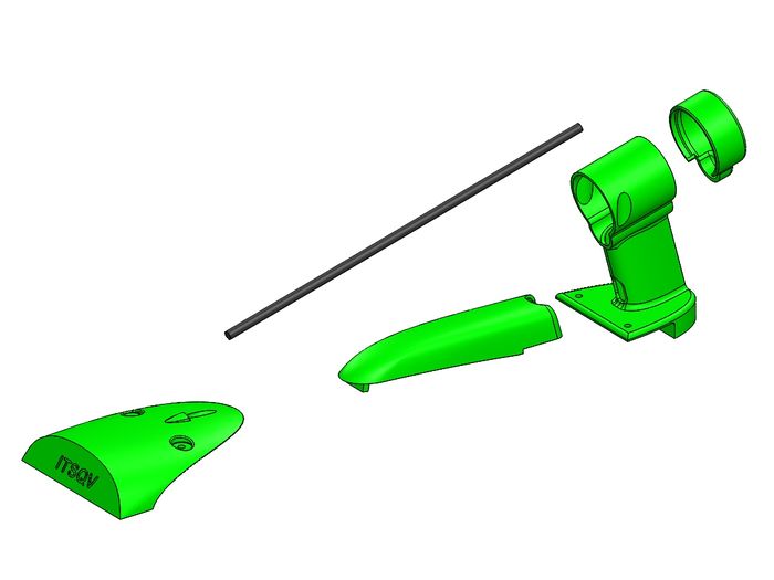
|
Now, because this is a low profile solution, the front foam canopy base needs to be carefully cut to match the front wing mount piece. Below is a picture of mine with the foam piece cut to match and a spring latch added to replace the magnet. Shown with a 2216 motor and an 8" Aeronaut folding prop.
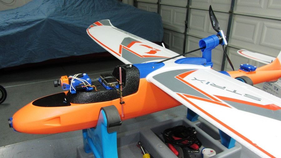
|
Also available, a longer 1 piece canopy to go with all of this. Sure makes the plane look slippery!
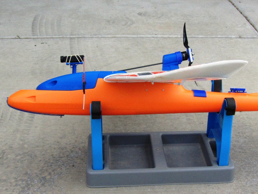
|
Roll Gimbal!
Finally got around to printing the low profile canopy with my standard 4 bolt mount to fit my Pan and Tilts and the same Brushless Roll Gimbal I use on my Mini Talon. It does add a fair amount of weight but the video result are awesome and so worth it!
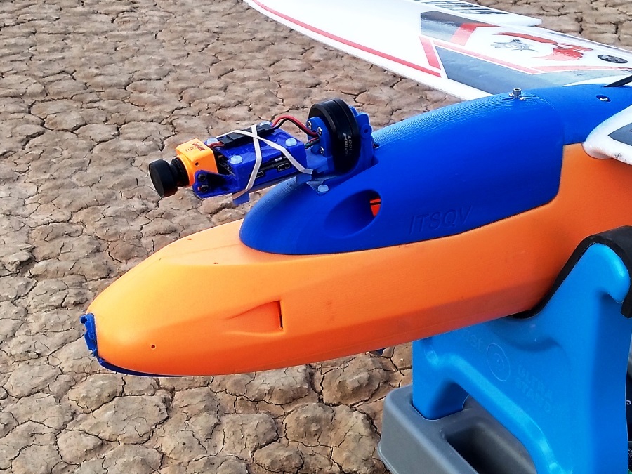
|
| Mounted with a RunCam Split |
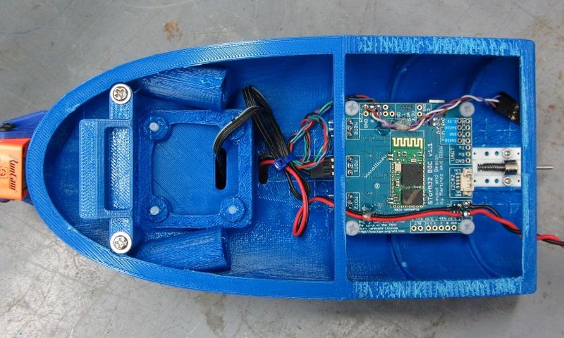
For control I am using a Storm32 V1.1 BGC control board which works very well and it has an integrated Bluetooth module for easy connection and tuning. (video below)
|
| Mounted with a RunCam Split |
Roll Gimbal Video
Here you can see a short demo that has no post processing for stability. There is a very small amount of yaw wobble and a little nose bobing caused by the FC which needs a little tuning.
|
Roll Gimbal test - 4 October, 2018 |
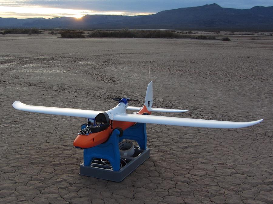
Parting Shot
|
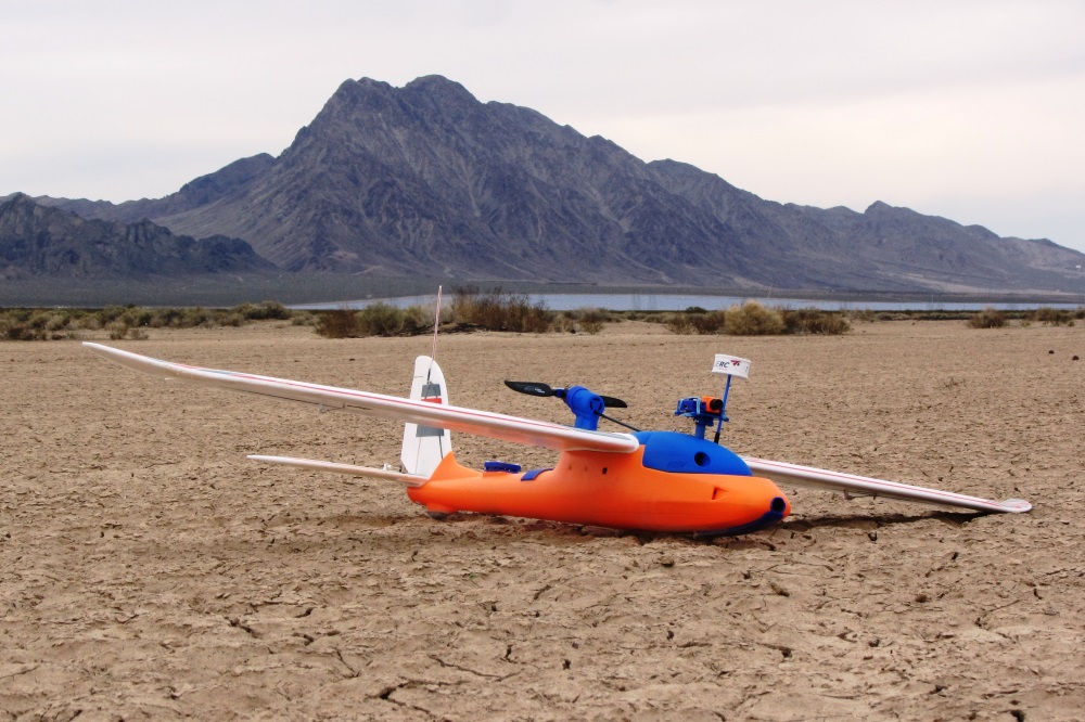
| (That "lake" in the background is actually a solar plant!) |
| |
The Strix Stratosurfer has been converted to a Twin Tractor setup and can now be found on a new page! |
Project 3D Print Files
All parts can be found on the Strix Stratosurfer parts catalog page.
See Also
Some of the Vendors I used for this project
Comments? Questions?
