Difference between revisions of "FinwingHobby FPV Penguin"
(→Comments? Questions?) |
|||
| (One intermediate revision by the same user not shown) | |||
| Line 1: | Line 1: | ||
| − | [[File:BTI.png|link= | + | [[File:BTI.png|link=AIRCRAFT|Air-Force]]<br> |
<i>December 2012</i><br> | <i>December 2012</i><br> | ||
| Line 454: | Line 454: | ||
<br><br><br> | <br><br><br> | ||
[[Category:Contents]] | [[Category:Contents]] | ||
| + | [[Category:Planes]] | ||
Latest revision as of 23:38, 4 February 2016
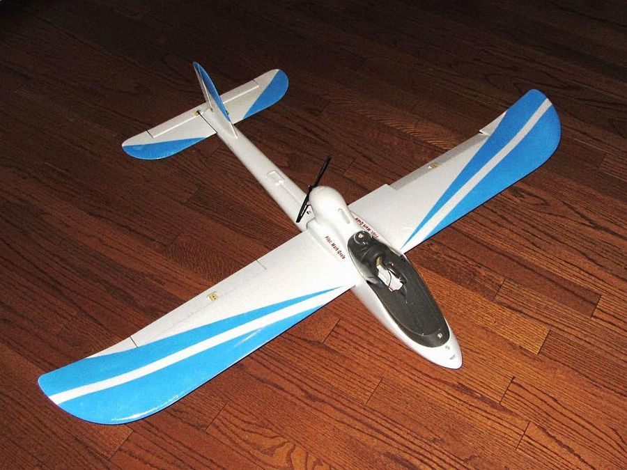
After building and flying multiple quads both FPV and LOS, I have decided to scratch the longer range itch with this new plane from ReadyMadeRC. This build log does not go over the stuff you would find in the manual but rather it is my own modifications and substitutions. One note about this particular build, I bought nothing for the plane you see here as I used parts and pieces I already had. So, with that said, the parts list will reflect prices I found online even though I may have paid something different.
Enjoy - Mark
General Specifications
Distributor - ReadyMadeRC.com
Aircraft - FinwingHobby Penguin
Build Date - December, 2012
| Airframe Type - | Mid Wing Power Glider | Flying Type - | Powered FPV Glider | |
| Wingspan = | 67 inches | Length = | 49 inches | |
| Wing Area = | 3.9 sq. feet | All-Up Weight = | 69.3 oz. | |
| Motor - | Turnigy SK3530/1400 | Wing Load = | 17.8 oz/sq. ft. | |
| Propeller - | 9 x 6 Various | Power = | 444 watts | |
| Thrust = | 48oz | Thrust/Weight = | 0.69 | |
| Battery Type - | 3S2P Lipo | Capacity = | 5400mah/35C | |
Build Review
A straight forward build with only a few mods and substitutions.
Component List
The component list includes all the major components needed. What is not shown are additional fasteners tie-wraps, connectors, aluminum materials, etc. The quantities shown are for a single build and do not reflect spares such as extra props or battery packs.
| Item (as of June 22, 2012) | Price | Qty | Sub-Tot |
| Base Penguin Kit | $109.95 | x1 | $109.95 |
| SK3530-1400Kv (link = current equivalent) | $18.36 | x1 | $18.36 |
| Hobbywing Platinum 60 ESC | $55.00 | x1 | $55.00 |
| Zippy Compact 2700mAh 3S 25C Lipo Pack | $14.73 | x2 | $29.46 |
| ArduPilot Mega 2.5 Flight Controller | $229.99 | x1 | $229.99 |
| 690 TVL Pixim Seawolf Camera, 3.6mm Lens | $66.99 | x1 | $66.99 |
| 800mW 1300MHz Video Transmitter | $59.99 | x1 | $59.99 |
| 1.3Ghz Cloverleaf Antenna | $29.99 | x1 | $29.99 |
| Low Pass Filter for 1.3Ghz Antenna | $26.99 | x1 | $26.99 |
| FrSky V8FR-II Receiver | $27.99 | x1 | $77.99 |
| Rudder Servo | $3.95 | x1 | $3.95 |
| Wing/Elev Servos | $20.02 | x3 | $60.06 |
| Total- | $718.72 |
Fuse - Elevator Linkage
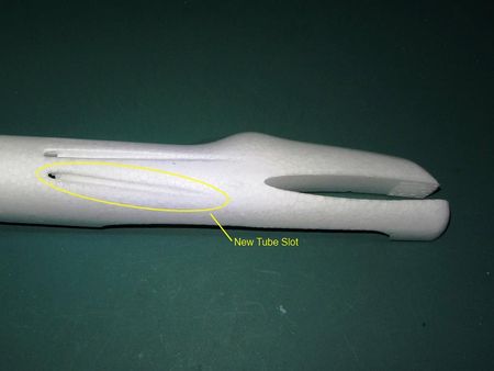
Starting with the fuselage I heard there were issues with the way the linkage for the elevator would get snagged in the grass on take-off and landing. The solution, of course, is to move the linkage to the top of the elevator which is what I did. It is a simple thing to remove the plastic guide tube, cut a new exit slot in the outside and inside of the fuse and re-glue the guide tube. I made the new slot by heating up a piece of .048 wire and simply laying it on the foam. I did the same on the inside.
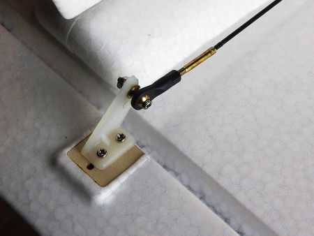
I then decided to get rid of all the kit linkage and make my own. The kit comes with copper (??) control horns and metal pushrod holders. Given the fact FPV systems can be prone to eletrical noise, I decided to use Dubro nylon horns and heavier control wire throughout. On the elevator I replaced the long wire rod with a carbon fiber piece. This CF rod is .060" (1.5mm) diameter and on the elevator end, I epoxied a Dubro 2-56 brass coupler with the threads cut to 3/8" (10mm). I prepped the socket end of the coupler by scratching up the inside with a wire pick and scrubbing it out with alcohol using a very tiny bottle brush from a paint sprayer kit. I prepped the CF rod by lightly scuffing it with 400 grit sandpaper. I used 30 minute epoxy to secure it in the coupler.
|
|
| The new control rod slot | Elevator detail with carbon rod and nylon control horn |
|
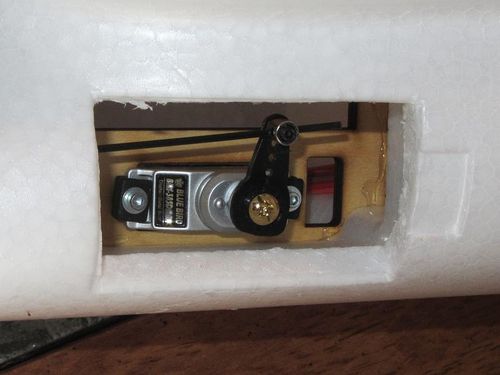
| Elevator servo detail |
Fuse - Landing Gear
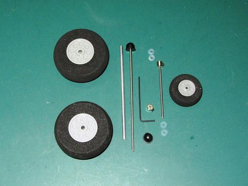
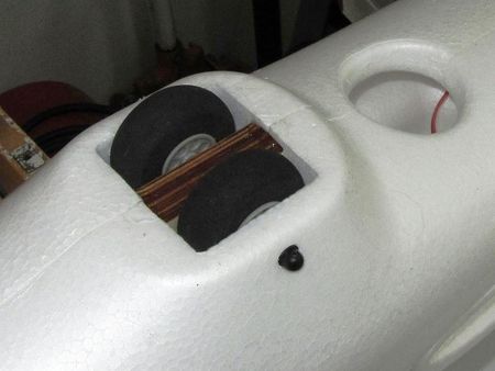
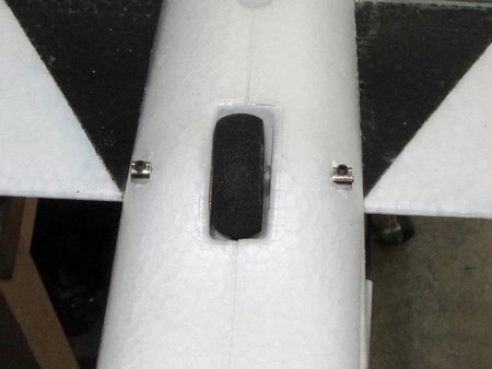
The landing gear have a couple issues. They are very loose and wobbly thus being generators of vibration and second, they are permanently glued in which makes it very difficult to repair a broken or worn-out wheel. So, what I did was drill out the fuse, pull out and throw away the LG shafts and replae it all with removable hardware. The weight adder for this was only 4 grams.
|
| New hardware pieces |
|
|
| Main gear showing Dubro collars | Rear wheel with standard collars |
Motor and Mount
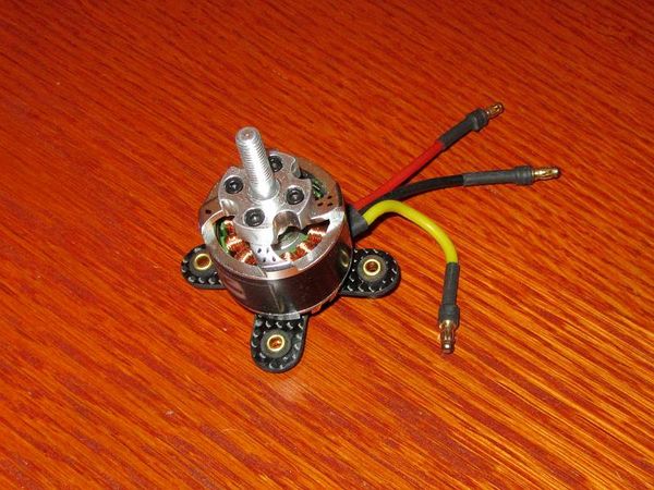
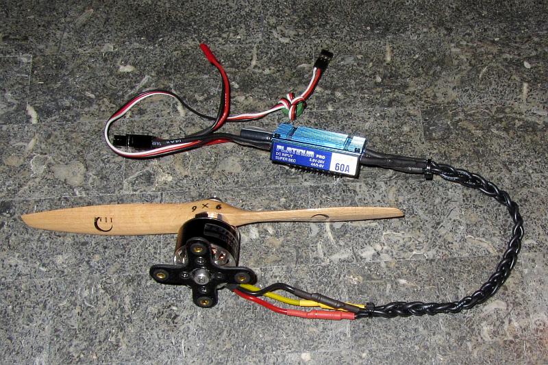
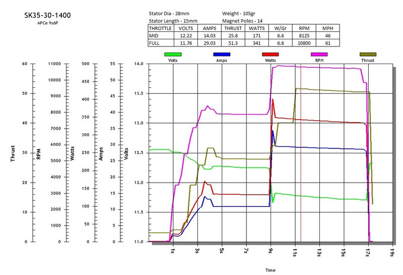
The motor, which was something I had in a drawer (with many, many others!) is the old Turnigy SK2 design and is no longer sold. The first thing I did here was dynamically balance the motor. Dynamic balancing can go a long way to making killer GoPro videos (my GoPro is hard mounted and shows zero jello!). Then I extended the ESC motor wires and braided them to help with interference.
Next up I built a simple vibration isolation mount (as added vibration insurance) out of a piece of 2mm carbon fiber plate, some rubber grommets and brass servo sleeves.
|
| The complete power system |
|
| Test data for the SK3530-1400 |
|
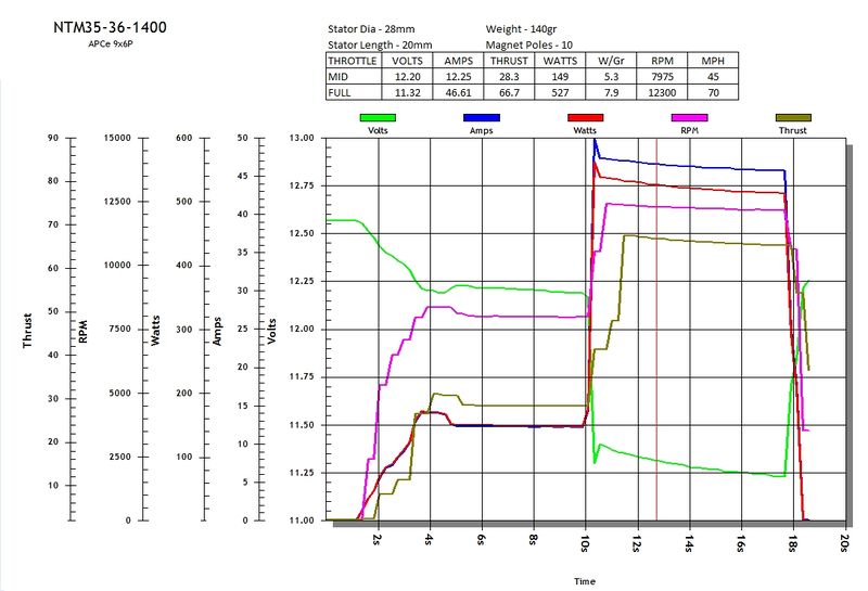
| Test data for the NTM35-36-1400 |
Props
I want to get the most efficient power system and this usually means a high quality prop. With that I threw five 9 x 6 and a 9 x 5 prop on the bench tester with a 3S pack and the Penguin motor to see what they would do. The props I selected for this are well known:
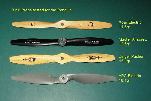
|
| The first four tested props |
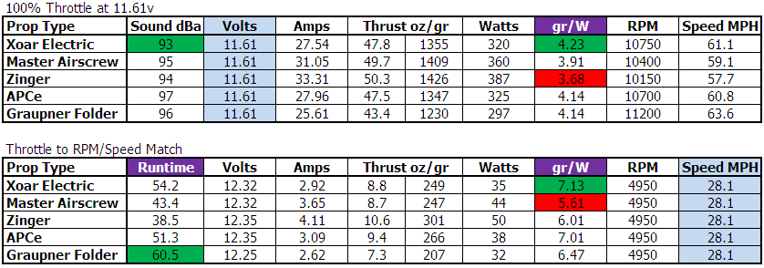
Here are test results using the SK3530 on 3S:
These charts represent static performance which does not take in to account prop unloading in flight or the fact this type of aircraft doesn't see a lot of 100% throttle. They also do not take into account airframe drag. What they do show are the efficiency differences and there are no real surprises in this test. The numbers highlighted in green are the best and red the worst. All props except the Graupner eProp are 9 x 6. The Graupner is a 9 x 5.
On the top chart all tests are normalized on the supply voltage. This is done by running each test at wide open throttle until the test voltage (11.61v) is reached. This gives a good view of the differences in propellor performance. The column, "T/100W", is an efficiency measure of thrust per 100 watts.
The bottom chart was normalized on RPM and prop speed. This shows how each prop performs relative to keeping a constant slow speed. The first column, runtime, is a theoretical maximum time at the listed steady state, this assumes an 80% discharge.
Ardupilot Flight Control
I selected the Ardupilot flight contoller because of excellent reviews, it has Loiter (position hold) and Return to Launch (home) functions and it has a solid failsafe program. I also found the MinimOSD which is an add on OSD, is really nice with two fully configurable screens and a display on/off function.
As far as mounting, I decided to make an easily removable tray for the flight controller directly under the CG. I came up with a simple 2-7/8" x 5-1/5" piece of 1/16" plywood with two screws in the front and a plywood, slide in, hold down in the rear.
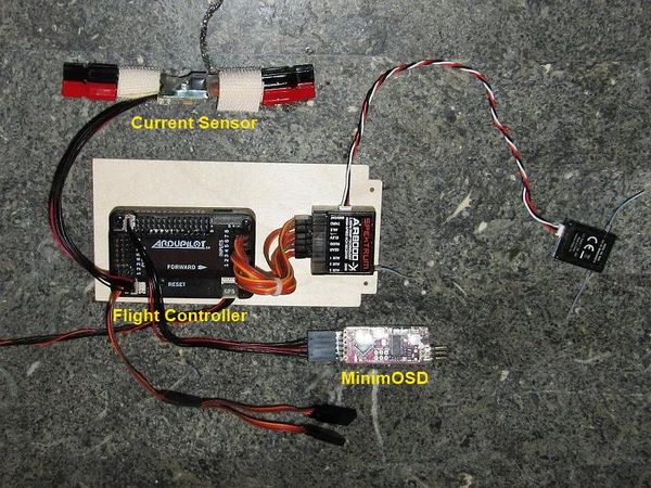
|
| Ardupilot component tray |
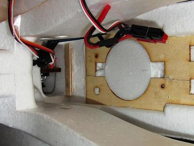
|
| Component tray rear mount |
I then burned a hole in the fuse side so that I could access the USB port without having to disconnect and remove everything. I also added a USB 5 pin mini converter which also serves as a port extension.
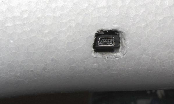
|
| Ardupilot USB port access |
The Penguin comes with velcro strips down the inside of the fuse so I wrapped the battery wires in hook velcro and stuck the power module to the side.
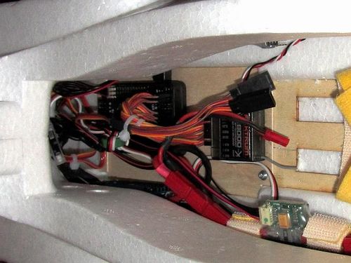
|
| All in and ready |
For the GPS unit, I used four long nylon 3mm srews and nuts. I hot-wired four holes in the top of the fuse midway between the motor and the tail and used Gorilla Glue on the screws to secure them into the foam.
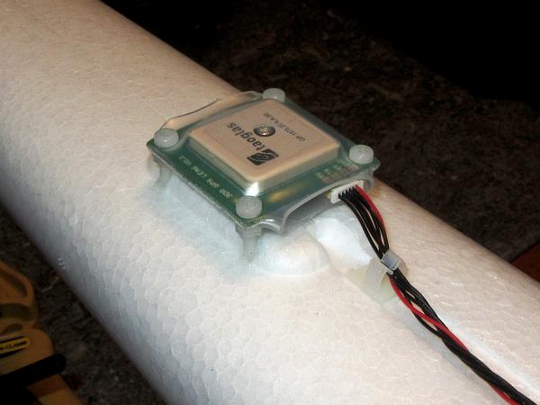
|
| The GPS unit shrink wrapped and mounted on nylon posts |
Camera Deck
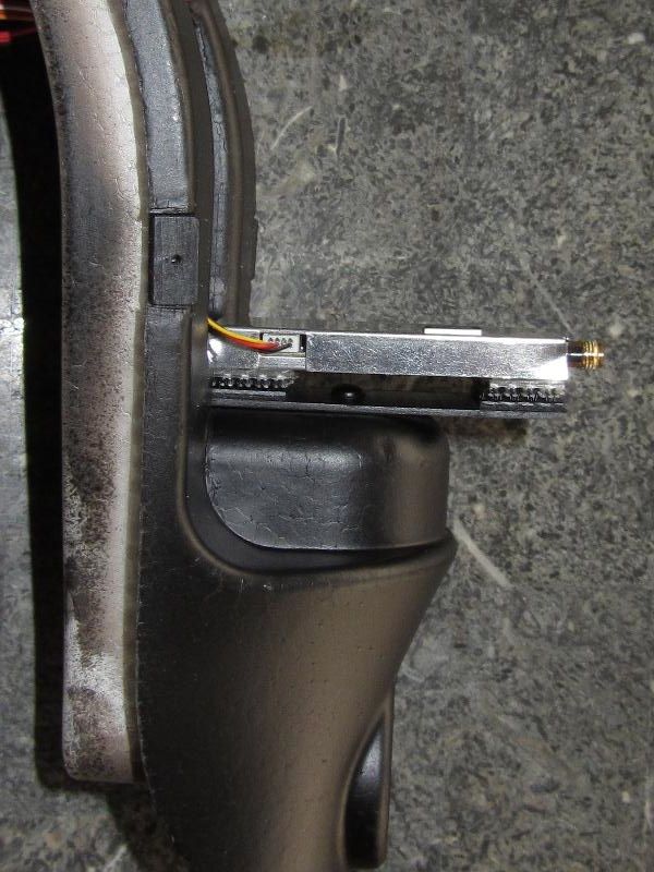
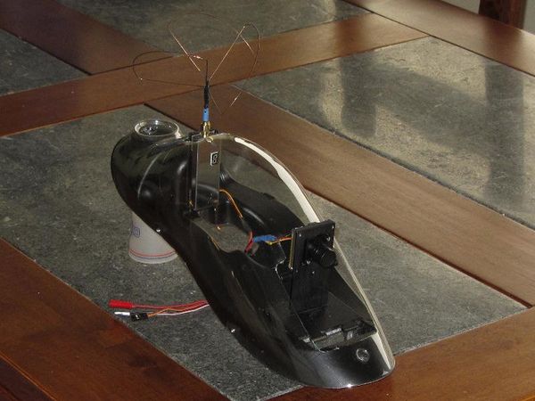
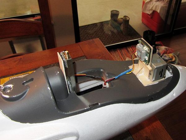
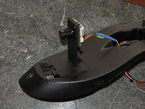
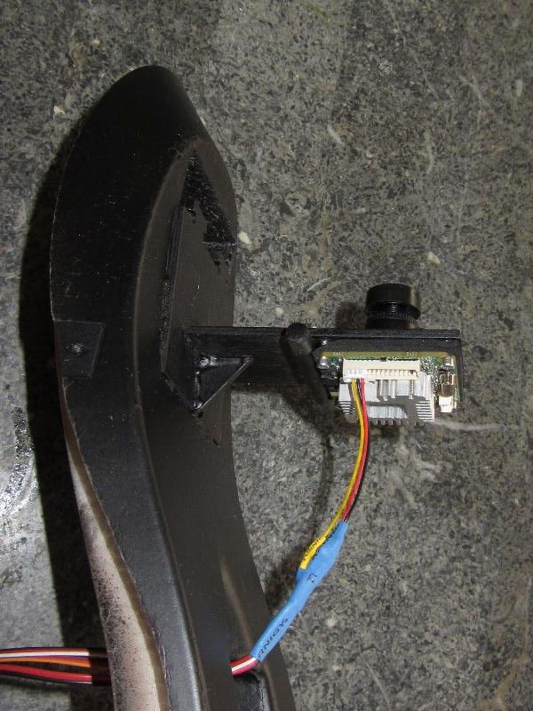
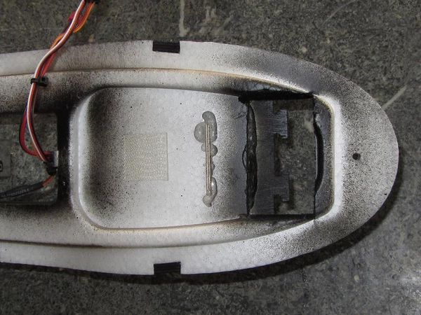
The camera deck was the last part to build and there are a lot of examples to look at. I opted to keep it simple for this first version with a fixed GoPro mount and fixed FPV camera mount. I made the camera mount out of 3/32" plywood and a piece of 1/4" dowel. The verticle FPV mount goes through the deck piece and the foam underneath for support. I cut out "T" tabs on the front of the mount plate for securing rubber bands around the GoPro securely. I used Gorilla Glue for all but the dowel which was epoxied.
|
| Pre-paint fit up |
|
| Front view with Pixm Seawolf FPV Camera mounted |
|
| Rear view of the FPV camera mount |
|
| Detail showing the FPV mount through the bootom of the foam deck |
Final Shots
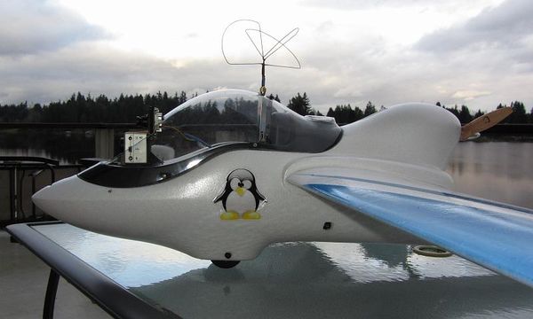
|
| Canopy profile |
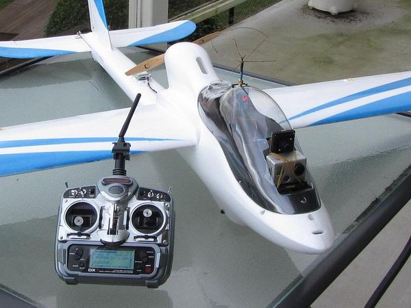
|
| Camera deck close up |
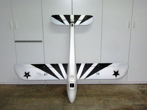
|
| The bottom scheme! |
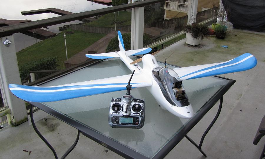
|
| Ready to go! |
And now a video!!!
|
First FPV Flight! |
Updates
- Moved the GoPro and FPV camera mount vertically up 3/8" (10mm) to get rid of the nose showing.
- Added an external battery plug/switch for easier connecting and disconnecting.
- Added nylon wire covering on all multistrand cables
- Installed an NTM3536/1400 with a Aeronaut Cam Folder, 9x6
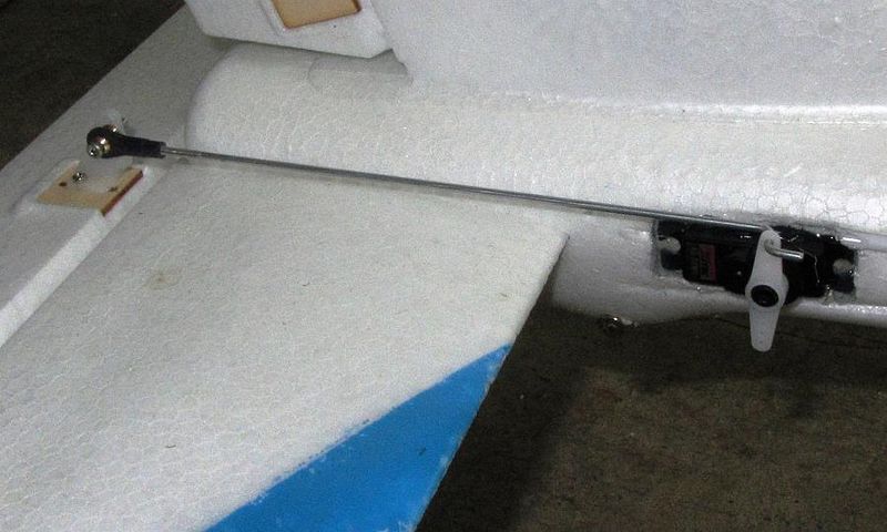
- Changed the Elevator servo to Hitec HS82MG and moved it to the tail which removes the tail wieght too.
|
| New Elevator Servo! |
- Current layout (May 4, 2013)

|
| Where everything sits |
See Also
Vendors used for this project
Comments? Questions?
